background image

CONTENTS

© 2019 IRONRIDGE, INC. VERSION 1.8

BX SYSTEM INSTALLATION MANUAL - 1

DISCLAIMER 1

RATINGS 2

MARKINGS 2

CHECKLIST 3

OVERVIEW 4

INSTALLATION STEPS (QUICK GUIDE) 

5

1. MARK LAYOUT 

6

2. PLACE CHASSIS 

6

3. MOUNT MLPE (OPTIONAL) 

6

4. LAY BALLAST 

7

5. ANCHOR SYSTEM (OPTIONAL) 

7

6. INSTALL MODULES 

8

7. COMPLETE BONDING 

8

8. PV MODULE GROUNDING LUGS 

9

STRING INVERTER MOUNTING KIT (OPTIONAL) 

9

ELECTRICAL DIAGRAM 

10

MODULE COMPATIBILITY 11

MODULE 

COMPATIBILITY 


12

MODULE 

COMPATIBILITY 


13

MODULE 

COMPATIBILITY 


14

MODULE 

COMPATIBILITY 


15

DISCLAIMER

This manual describes proper installation procedures and provides necessary standards required for product reliability. 

Warranty details are available at 

IronRidge.com

. All installers must thoroughly read this manual and have a clear 

understanding of the installation procedures prior to installation. Failure to follow these guidelines may result in property 

damage, bodily injury or even death

.

IT IS THE INSTALLER’S RESPONSIBILITY TO:

•  Ensure safe installation of all electrical aspects of the array. All electrical installation and procedures should be 

conducted by a licensed and bonded electrician or solar contractor. Routine maintenance of a module or panel shall 

not involve breaking or disturbing the bonding path of the system. All work must comply with national, state and local 

installation procedures, product and safety standards.

• 

Comply with all applicable local or national building and fire codes, including any that may supersede this manual.

•  Ensure all products are appropriate for the installation, environment, and array under the site’s loading conditions.

•  Use only IronRidge parts or parts recommended by IronRidge; substituting parts may void any applicable warranty.

•  Review the 

Design Assistant

 to confirm design specifications.

•  Ensure provided information is accurate. Issues resulting from inaccurate information are the installer’s responsibility.

•  Ensure bare copper grounding wire does not contact aluminum and zinc-plated steel components, to prevent risk of 

galvanic corrosion.

•  If loose components or loose fasteners are found during periodic inspection, re-tighten immediately. If corrosion is 

found, replace affected components immediately.

•  Provide an appropriate method of direct-to-earth grounding according to the latest edition of the National Electrical 

Code, including NEC 250: Grounding and Bonding, and NEC 690: Solar Photovoltaic Systems.

•  Disconnect AC power before servicing or removing modules, AC modules, microinverters and power optimizers.

•  Review module manufacturer’s documentation for compatibility and compliance with warranty terms and conditions.


Summary of Contents for BX SYSTEM

Page 1: ... 2019 IRONRIDGE INC VERSION 1 8 BX SYSTEM INSTALLATION MANUAL i BX SYSTEM INSTALLATION MANUAL ...

Page 2: ...involve breaking or disturbing the bonding path of the system All work must comply with national state and local installation procedures product and safety standards Comply with all applicable local or national building and fire codes including any that may supersede this manual Ensure all products are appropriate for the installation environment and array under the site s loading conditions Use o...

Page 3: ...pward 5 PSF lateral Actual system structural capacity is defined by PE stamped project designs CLASS A SYSTEM FIRE RATING PER UL 2703 Any System Tilt with Modules Types 1 2 3 13 19 25 29 on Low Slope Roofs 9 5 degrees Any module to roof gap is permitted with no perimeter guarding required This rating is applicable with any IronRidge or 3rd party roof attachment and with or without concrete blocks ...

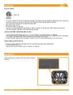
Page 4: ...sis 10 BX Chassis 8 Module Bonding Jumper 38 Row Bonding Jumper Bottom Clamp Top Clamp Height Varies PV Module Grounding Lug MLPE Mounting Hardware UNLESS OTHERWISE SPECIFIED 1 PACKAGE PER BX CMA MI M1 PCK BX MIPO MOUNTING ASSEMBLY 20 PCK INST REV A RELEA ITEM NO PART NUMBER DESCRIPTION QTY REV 1 23 3118FB 075 FLANGE HEAD CAP SCREW 5 16 18 X 3 4 SS 1 A 2 BX 31CN 015 CAGENUT 1 A Q A MFG APPR ENG AP...

Page 5: ... lbs 2 lbs for full size Compressive Strength requirement 3000 PSI min MODULE CLAMPING Top Clamps are module frame height specific and accommodate most common module sizes 30mm 32mm 33mm 35mm 38mm 40mm 46mm ARRAY GROUNDING Only one PV Module Grounding Lug is required per continuous array regardless of array size Use the IronRidge PV Module Grounding Lug PV LUG 01 A1 Alternately the following groun...

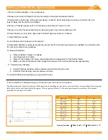
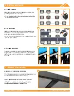
Page 6: ...ion a Place all Bottom Clamps on Chassis b Land all panels on Chassis c Place all Top Clamps and ensure proper alignment and engagement of the Bottom Clamp d Make sure that all Clamps are fully engaged and square to the module and torqued appropriately 11 Complete Array Bonding a Install 8 Module Bonding Jumpers between all modules along the rows b Install 38 Row Bonding Jumpers between all rows 1...

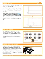
Page 7: ...back mark the South Array Edge at least 8 away from the setback This will ensure that no part of the Chassis is in the setback Measure Chassis spacing refering to table on Page 5 and chalk out 3x 25 rows Then measure out the Chassis locations by marking along each row module width plus 3 8 These layouts are useful for maintaining a straight line at the start of the array Once started the rest of t...

Page 8: ... minimum an 8 x 1 5 8 Galvanized Strut Channel with slotted holes through the two Chassis onto the L Feet using the provided 3 8 Bolt with 1 1 4 washer to a Channel Nut not provided Torque Nut to 250 in lbs C FINISH ANCHORS Assemble an L Foot onto the FRA Anchor and flashing membrane where applicable using the 3 8 Bolt and Flat Washer torqued to 250 in lbs Then install L Foot and Flat Roof Attachm...

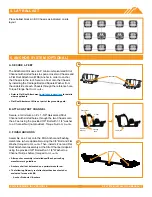
Page 9: ...located in the middle of the Chassis to properly space modules C SECURE MODULES To secure a module first pull the Bottom Clamp until it is snug against the inner flange of the module Then place the Top Clamp and Flange Nut over the bolt and torque to 120 in lbs A MODULE TO MODULE BONDING The 8 Bonding Jumper is an electrial bonding jumper that can be used for module to module bonding New jumpers s...

Page 10: ... 8 PV MODULE GROUNDING LUGS FLANGE NUT GROUNDING LUG BOLT B STRING INVERTER MOUNTING KIT OPTIONAL The String Inverter Mounting Kit creates a mounting platform for inverters on top of the BX Chassis A CROSS RAILS Cut provided rails to length as needed Install four Cage Nuts in the square holes on the edges of the Chassis Then install an L Foot into each Cage Nut location using a 5 16 bolt tightened...

Page 11: ... 2019 IRONRIDGE INC VERSION 1 8 BX SYSTEM INSTALLATION MANUAL 10 ELECTRICAL DIAGRAM ...

Page 12: ...M DGT and zz can be blank HV F B or F BH ASUN ASUN modules with 35 and 40 mm frames ASUN xxx YYZZ aa Where YY can be 60 or 72 ZZ can be M or MH5 and aa can be blank or BB Auxin Auxin modules with 40 mm frames AXN6y6zAxxx Where y can be M or P z can be 08 09 10 11 or 12 and A can be F or T Axitec Axitec Modules with 35 and 40 mm frames AC xxxY aaZZb Where Y can be M P or MH aa can be blank 125 or 1...

Page 13: ...dules with 40 45 and 50 mm frames HSLaaP6 YY 1 xxxZ Where aa can be either 60 or 72 YY can be PA or PB and Z can be blank or B Hanwha Q CELL Hanwha Q CELLS Modules with 32 35 40 and 42mm frames aaYY ZZ xxx where aa can be Q or B YY can be PLUS PRO PEAK LINE PRO LINE PLUS PLUS DUO or PEAK DUO and ZZ can be G3 G3 1 G4 G4 1 L G2 L G2 3 L G3 L G3 1 L G3y L G4 L G4 2 L G4y LG4 2 TAA BFR G3 BLK G3 BFR G...

Page 14: ...an be C K T or W and bb can be A3 A5 B3 G3 G4 J5 K4 L5 N5 or V5 Longi Longi modules with 30 35 and 40 mm frames LRa YYZZ xxxM Where a can be 4 or 6 YY can be blank 60 or 72 and ZZ can be blank BK BP HV PB PE PH HBD HPB or HPH Mission Solar Mission Solar modules with 33 and 40 mm frames MSEbbxxxZZaa Where bb can be blank or 60A ZZ can be blank MM SE SO SQ SR or TS and aa can be blank 1J 4J 4S 5K 5T...

Page 15: ...n be blank 20 25 40 or 45 CC can be blank 60 or 72 YYY can be blank BDE MAE MAI MBE MBI MCE or MCI and Z can be V M 10 P 10 or P 15 Seraphim Energy Group Seraphim modules with 30 35 and 40 mm frames SEG aYY xxxZZ Where a can be blank 6 or B YY can be blank MA MB PA or PB and ZZ can be blank BB BG BW HV WB WW BMB BMB HV BMA HV BMA BG Seraphim USA Seraphim modules with 35 and 40 mm frames SEG aYY xx...

Page 16: ...ard G3 or G4 or InvisiMount G5 40 and 46 mm frames SPR Zb xxx YY Where Z is either A E P or X b can be blank 17 18 19 20 21 or 22 and YY can be blank BLK COM C AC D AC E AC BLK E AC G AC BLK C AC or BLK D AC Sunspark Sunspark modules with 40 mm frames SYY xxxZ A Where YY can be MX or ST and Z can be M MB M3 M3B P or W and A can be 60 or 72 Suntech Suntech Modules with 35 40 and 50mm frames STPxxxy...

Reviews: