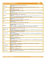
© 2019 IRONRIDGE, INC. VERSION 1.8
BX SYSTEM INSTALLATION MANUAL - 9
7. COMPLETE BONDING (CONTINUED)
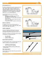
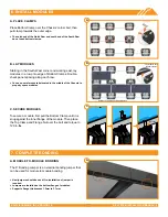
B. ROW-TO-ROW BONDING
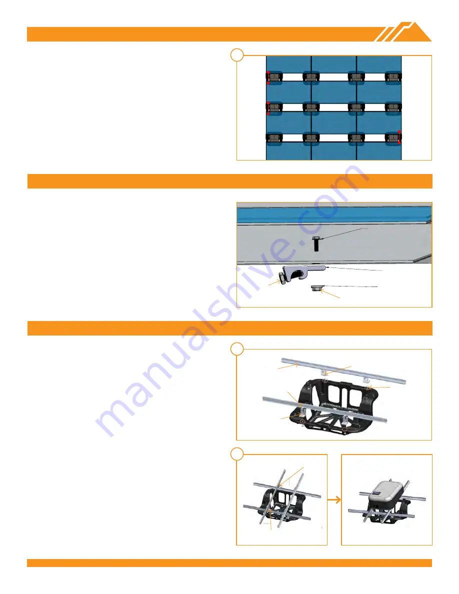
The 38" Bonding Jumper is an electrial bonding jumper
that should be used for row to row bonding by securing
Clips to inner flanges on long side of a module from each
row, as shown. Tapping Clips into place may be required
for modules with thicker flanges.
➢
The bonding does not need to take place on the same side of the
array, so long as every row is bonded to the next row.
Ground each continuous array by securing a PV Module
Grounding Lug to any module in the array.
➢
Only one PV Module Grounding Lug is required per continuous
array, regardless of array size. Reference module manufacturer’s
installation instructions for grounding location.
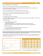
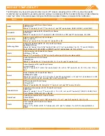
8. PV MODULE GROUNDING LUGS
FLANGE NUT
GROUNDING LUG
BOLT
B
STRING INVERTER MOUNTING KIT (OPTIONAL)
The String Inverter Mounting Kit creates a mounting
platform for inverters on top of the BX Chassis.
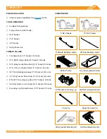
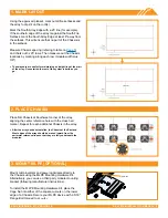
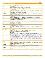
A. CROSS RAILS
Cut provided rails to length, as needed. Install four Cage
Nuts in the square holes on the edges of the Chassis.
Then, install an L-Foot into each Cage Nut location using a
5/16” bolt tightened to
80 in-lbs
. Attach rails to L-Feet using
3/8” T-bolt bonding hardware tightened to
250 in-lbs
.
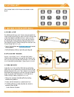
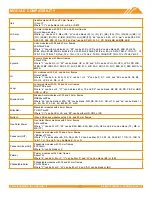
B. TOP RAILS
Assemble the top rails using four L-Feet on top of cross
rails. Install four L-Feet on top of the cross rails using
¼” T-bolt and nut tightened to 80 in-lbs. Attach top rails
to L-Feet using 3/8” T-bolt Bonding Hardware tightened
to
250 in-lbs
. Space top rails according to the mounting
requirements for the inverter being used.
A
B
60 in-lbs
20 in-lbs
Cross Rail (2x)
L-Foot (4x)
Cage Nut (4x)
5/16" Bolt (4x)
3/18" T-Bolt
Hardware (4x)
250 in-lbs (4x)
80 in-lbs (4x)

