© 2019 IRONRIDGE, INC. VERSION 1.8
BX SYSTEM INSTALLATION MANUAL - 4
OVERVIEW
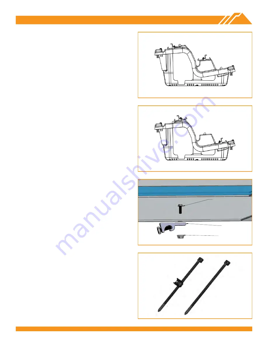
BX CHASSIS (5° & 10°)
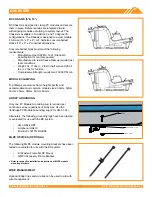
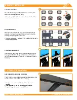
BX Chassis is designed to clamp PV modules and secure
them in place. Reference tabs are integrated to aid
with aligning modules according to system layout. The
Chassis is available in two SKUs: 5 and 10 degree tilt
configurations. The Chassis is designed to accommodate
4 full size (16” x 8” x 4”) or 8 half-size concrete ballast
blocks (16” x 8” x 2”) nominal dimensions.
Concrete ballast block must meet the following
requirements:
• Manufactured per ASTM C 1491 (Standard
specification for concrete pavers)
• Manufactured to resist freeze-thaw as required per
local conditions
• Weight: 14-17 lbs +/- 2 lbs for half size and 28-34
lbs +/- 2 lbs for full size
• Compressive Strength requirement: 3000 PSI min
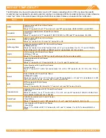
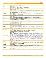
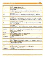
MODULE CLAMPING
Top Clamps are module frame height specific and
accommodate most common module sizes: 30mm, 32mm,
33mm, 35mm, 38mm, 40mm, 46mm.
ARRAY GROUNDING
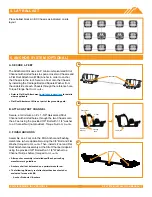
Only one PV Module Grounding Lug is required per
continuous array, regardless of array size. Use the
IronRidge PV Module Grounding Lug (PV-LUG-01-A1).
Alternately, the following grounding lugs have been tested
or evaluated for use with the BX system:
• Ilsco GBL-4DBT
• Amphenol HGLUI
• Burndy CL501TN, BGBS4
MLPE DEVICES (OPTIONAL)
The following MLPE module mounting brackets have been
tested or evaluated for use with the BX system:
• EcoFasten Frame MLPE Mount
• QMPV Accessory Frame Bracket
➢
Refer to respective installation instructions of MLPE module
mounting brackets.
WIRE MANAGEMENT
Optional Edge Clips and wire ties can be used to aid with
wire management.
FLANGE NUT
GROUNDING LUG
BOLT

