background image

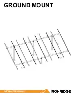
GROUND MOUNT

INSTALLATION MANUAL

Summary of Contents for GROUND MOUNT

Page 1: ...GROUND MOUNT INSTALLATION MANUAL ...

Page 2: ...y with all applicable local or national building and fire codes including any that may supersede this manual Ensure all products are appropriate for the installation environment and array under the site s loading conditions Use only IronRidge parts or parts recommended by IronRidge substituting parts may void any applicable warranty Review the Design Assistant and Certification Letters to confirm ...

Page 3: ...x Overcurrent Protective Device OCPD Rating 25A Max Module Size 25 6 ft Max Frameless Module Size for Canadian LTR AE 21 5 ft CAMO Specific Allowable Design Load Rating 50 PSF downward 50 PSF upward 15 PSF lateral LTR AE Canadian Load Rating 2400 Pa System Level Allowable Design Load Rating meets minimum requirements of the standard 10 PSF downward 5 PSF upward 5 PSF lateral Actual system structur...

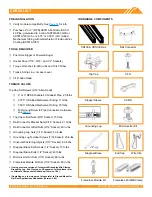
Page 4: ... Pipe Connection Hardware see page 5 Top Cap U Bolt Nuts 9 16 Socket 15 ft lbs Rail Connector Bracket Nuts 9 16 Socket 21 ft lbs Rail Connector U Bolt Nuts 9 16 Socket 60 in lbs Grounding Lug Nuts 7 16 Socket 80 in lbs Grounding Lug Terminal Screws 7 16 Socket 20 in lbs Universal Fastening Objects 7 16 Socket 80 in lbs Diagonal Brace Set Screws 1 2 Socket 15 ft lbs Diagonal Brace Bolts 1 2 Socket ...

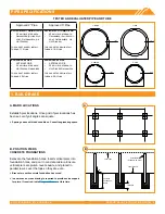
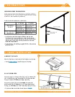
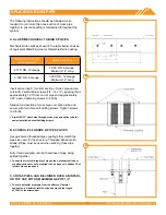
Page 5: ... install Diagonal Braces at this time A B Level Tops Vertical Pier Schedule 40 Pipe Level Ground 90 1 3 Depth Concrete Foundation Depth 1 BUILD BASE TESTED AND EVALUATED PIPE AND TUBE 216 in 3 5 in 3 PIPE 154 in 2 375 in 3 pipe 165 in 3 5 in 3 TUBING 109 in 2 375 in 2 Tubing Approved 2 Pipe Approved 3 Pipe ALLIED MECH TUBING 12 GA 50 ksi yield strength Galvanized Allied flot coat Gatorshield or Ho...

Page 6: ... Allied Tubing 16 ft lbs GROUND SCREW FOUNDATIONS Follow respective Ground Screw Manufacturer s installation methods for driving screws into soil Insert vertical piers into ground screws ensuring at least 18 of pier is inserted into ground screw Tested and or Evaluated Ground Screws 2 System 3 System Manufacture Model American Ground Screws N76 American Ground Screws N102 Krinner North America KSF...

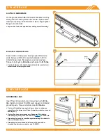
Page 7: ...rails should align with module manufacturer recommended clamping locations GROUNDING LUGS Insert T bolt in top rail slot and torque hex nut to 80 in lbs Install a minimum 10 AWG solid copper or stranded grounding wire Torque terminal screw to 20 in lbs Only one Grounding Lug required per continuous subarray regardless of subarray size Unless frameless modules are used see Page 10 If using Enphase ...

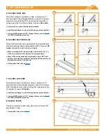
Page 8: ...t for each following module When reinstalling UFO move modules a minimum of 1 16 so UFOs are in contact with a new section of module frame When UFOs are loosened and re tightened ensure UFO T bolt bottoms out in rail channel before re torquing UFO to achieve full engagement between T bolt and rail If using Wire Clips refer to Page 9 C SECURE LAST END Place last module in position on rails a minimu...

Page 9: ...g bolt contacts the module flange edge D SECURE TO FRAME Rotate handle with an upwards motion until CAMO snaps into rail channel Ensure CAMO bonding pins are fully seated on top of module frame FRAME COMPATIBILITY CAMO has been tested or evaluated with all modules listed in the Module Compatibility section having frames within the referenced dimensions Be sure the specific module being used meets ...

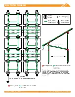
Page 10: ...nding Lug required per continuous subarray Cross Pipe Rail Cross Pipe UFO or CAMO Optional Cross Brace Grade Bonding Points Fault Current Ground Path Grounding Lugs and wire are not required in systems using certain Enphase microinverters or certain Sunpower modules Equipment grounding is achieved with the Engage cable for Enphase or the AC module cable system for Sunpower via their integrated EGC...

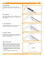
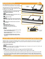
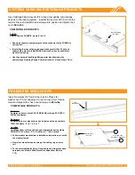
Page 11: ...ft lbs END CAPS WIRE CLIPS End Caps add a completed look and keep debris and pests from collecting inside rail Firmly press End Cap onto rail end End Caps come in sets of left and right Check that the proper amount of each has been provided For open structure installations you can use adhesive to secure the End Caps Wire Clips offer a simple wire management solution Firmly press Wire Clip into top...

Page 12: ... 9 ft lbs Pre drill 5 32 pilot holes through cross pipe and splice tube for easier installation of self drilling screws B SCHEDULE 40 GRADE B PIPE SPLICES Use galvanized threaded pipe couplings that match the pipe size used for the structure Threaded Schedule 40 Grade B Pipe must be used when splicing cross pipe together Fully thread coupling onto both sections of pipe being spliced together To en...

Page 13: ...nted to the same rail and connected to the same Engage cable are required The microinverters or Sunpower AC modules must be used with a maximum 20 A branch rated overcurrent protection device OCPD If an AC module is removed from a circuit for maintenance you must first disconnect AC power and then install a temporary EGC to bridge the gap by inserting an AC extension cable or via other NEC complia...

Page 14: ...ment grounding conductor to the PHAZRs is not required If installing in areas with ground snow loads greater than 40 psf and underneath a module install PHAZR devices as close as possible to module frame edge Use the number of IronRidge Microinverter kits allowed by the microstorage mounting flange Some will require 1 kit and others 2 kits COMPATIBLE PRODUCTS Sunforson Sunforson silver or black SF...

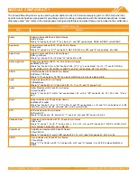
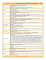
Page 15: ... M DG or M DGT and zz can be blank HV F B or F BH ASUN ASUN modules with 35 and 40 mm frames ASUN xxx YYZZ aa Where YY can be 60 or 72 ZZ can be M or MH5 and aa can be blank or BB Auxin Auxin modules with 40 mm frames AXN6y6zAxxx Where y can be M or P z can be 08 09 10 11 or 12 and A can be F or T Axitec Axitec Modules with 35 and 40 mm frames AC xxxY aaZZb Where Y can be M P or MH aa can be blank...

Page 16: ...odules with 40 45 and 50 mm frames HSLaaP6 YY 1 xxxZ Where aa can be either 60 or 72 YY can be PA or PB and Z can be blank or B Hanwha Q CELL Hanwha Q CELLS Modules with 32 35 40 and 42mm frames aaYY ZZ xxx where aa can be Q or B YY can be PLUS PRO PEAK LINE PRO LINE PLUS PLUS DUO or PEAK DUO and ZZ can be G3 G3 1 G4 G4 1 L G2 L G2 3 L G3 L G3 1 L G3y L G4 L G4 2 L G4y LG4 2 TAA BFR G3 BLK G3 BFR ...

Page 17: ...can be C K T or W and bb can be A3 A5 B3 G3 G4 J5 K4 L5 N5 or V5 Longi Longi modules with 30 35 and 40 mm frames LRa YYZZ xxxM Where a can be 4 or 6 YY can be blank 60 or 72 and ZZ can be blank BK BP HV PB PE PH HBD HPB or HPH Mission Solar Mission Solar modules with 33 and 40 mm frames MSEbbxxxZZaa Where bb can be blank or 60A ZZ can be blank MM SE SO SQ SR or TS and aa can be blank 1J 4J 4S 5K 5...

Page 18: ...can be blank 20 25 40 or 45 CC can be blank 60 or 72 YYY can be blank BDE MAE MAI MBE MBI MCE or MCI and Z can be V M 10 P 10 or P 15 Seraphim Energy Group Seraphim modules with 30 35 and 40 mm frames SEG aYY xxxZZ Where a can be blank 6 or B YY can be blank MA MB PA or PB and ZZ can be blank BB BG BW HV WB WW BMB BMB HV BMA HV BMA BG Seraphim USA Seraphim modules with 35 and 40 mm frames SEG aYY ...

Page 19: ...ndard G3 or G4 or InvisiMount G5 40 and 46 mm frames SPR Zb xxx YY Where Z is either A E P or X b can be blank 17 18 19 20 21 or 22 and YY can be blank BLK COM C AC D AC E AC BLK E AC G AC BLK C AC or BLK D AC Sunspark Sunspark modules with 40 mm frames SYY xxxZ A Where YY can be MX or ST and Z can be M MB M3 M3B P or W and A can be 60 or 72 Suntech Suntech Modules with 35 40 and 50mm frames STPxx...

Page 20: ...72 ZZ can be M and A can be GH Jinko Jinko frameless modules JKMxxxPP DV Prism Solar Prism Solar frameless modules BiYY xxxBSTC Where YY can be 48 60 60S 72 or 72S Risen Risen frameless modules RSMyy 6 xxxZZ Where yy can be 60 72 120 or 144 and ZZ can be MDG or PDG Stion Stion frameless modules STL xxx or STL xxxA Sunpreme Sunpreme frameless modules GXB xxxYY Where YY can be blank or SL Trina Trin...

Reviews: