background image

Page 4 


   |     

ironridge.com

     |     (800) 227-9523

  2013 v1.13     


support@

Rails with Integrated Grounding

Installation Manual

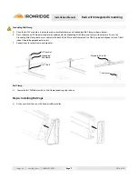
A.  Determine the appropriate flashing required for your roof type and 

project.  Install flashing per manufacturer’s requirements. 

B.  Mount all the L-feet to the roof in the desired locations using a minimum 

5/16” x 3” long Lag Bolt.  The 5/16” Lag Bolt attached to a structural roof 

member such as a rafter.   For metal  or tile roofs, install a mount suitable 

for the application, per mount manufacturer’s requirements.     


Note:


 The roof attachment spacings are defined by many variables such as site 

conditions, rail type and roof structure.  Refer to the IronRidge Certification letters 

or online Design Assistant to determine appropriate attachment spacing.  

Assembly Steps

Step 1. Install Applicable Roof Flashing and L-feet

Step 3. Rail to Rail Connections

Step 2. Attaching Rails To L-Feet

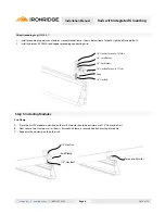
A.  Slide the 3/8” bolts into rail side slot.  Space bolts to match the L-feet 

spacing.  

B.  Loosely attach rail to L-feet using 3/8” hardware.   Position rail at desired 

height and level.  Once level torque 3/8” hardware to 236 in-lbs (dry). 
Move to Step 3 for Rail to Rail Connections then repeat Step 2 for each 
L-foot connection.

Note:


 Attaching rails to L-Feet may be performed before or after making rail-to-

rail connections, depending on the installer’s preference.

Note:


 This connection requires proper grounding on rails with grounding lugs by using one of the two following Rail to Rail Connection 

methods.  For rails without lugs, use the Internal Splice and self-drilling screws without the grounding strap and star washers (See Page 8).  For 

rows exceeding 50 feet of rail, IronRidge recommends the Rail to Rail Expansion Joint.  Expansion joints prevent the potential buckling of rails 

due to thermal expansion.  At the installer’s discretion, a Rail to Rail Expansion Joint may also be used at  lengths of less than 50 feet of rail.  

Rail to Rail (Basic) Connection

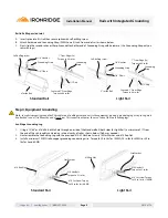
A.  Insert internal splice into first rail then secure splice with hardware and Grounding Strap (9AWG).  Attach and assemble as shown. 

B.  Next, slide second rail over splice and secure with hardware on opposite end of Grounding Strap.  

C.  Repeat this procedure for remaining Rail to Rail Connections.  (Use Grounding Strap only on rails with lugs.)

Standard 

Rail 

      Light 

Rail

Centered 1” From Edge

Torque to 84 in-lbs

6” inside Rail 

Self-drilling screw

Grounding 

Strap

Star Washer

Centered 1” From Edge

Torque to 84 in-lbs

Centered 1” From Edge

Torque to 84 in-lbs

3” inside Rail 

Self-drilling screw

Grounding 

Strap

Star Washer

Centered 1” From Edge

Torque to 84 in-lbs

Summary of Contents for Light

Page 1: ...Installation Manual 2013 Edition v1 13 A complete manual for the installation of IronRidge s rail systems with integrated grounding Standard XRS and Light XRL Rails with Integrated Grounding Conforms to UL SUB 2703 4008083 ...

Page 2: ...he IronRidge Standard XRS and Light XRL Rail Mounting Systems with Integrated Grounding Customer Support Tools Required For Assembly Torque Values Component List Assembly Steps 1 3 4 Assembly Steps 3 4 5 Assembly Steps 4 5 6 Assembly Step 5 6 7 Warranty Information 9 TOC ironridge com 800 227 9523 2013 v1 13 support Module Clamp Table 2 Rails with Integrated Grounding Installation Manual 8 ...

Page 3: ...ing devices including lag screws have adequate pullout strength and shear capacities as installed VI Maintaining the waterproof integrity of the structural support or roof including selection of appropriate flashing VII Ensuring safe installation of all electrical aspects of the PV array VIII Ensuring that PV module is installed per module manufacturer s installation requirements the PV module man...

Page 4: ... Use the following torque values in this assembly Module Clamp Table Millimeters Inches End Clamp Grounding Mid Clamp 31 0 32 5 1 22 1 28 29 7000 125 RS GD MCL 200 33 3 34 8 1 31 1 37 29 7000 134 RS GD MCL 200 34 8 36 8 1 37 1 45 29 7000 224 RS GD MCL 225 39 0 41 0 1 53 1 61 29 7000 157 RS GD MCL 225 41 1 42 7 1 62 1 68 29 7000 165 RS GD MCL 250 42 7 44 2 1 68 1 74 29 7000 171 RS GD MCL 250 45 0 4...

Page 5: ...aches to L foot and provides support for the PV modules Grounding Mid Clamp Secures PV modules to rails and provides grounding to the rail and between the two adjacent modules Internal Splice Provides a structural connection when connecting rails End Clamp Secures PV modules to rails utilizing the rail top slot End Cap Caps off the end of the rail and prevents the collection of debris inside rail ...

Page 6: ...onnection Note Attaching rails to L Feet may be performed before or after making rail to rail connections depending on the installer s preference Note This connection requires proper grounding on rails with grounding lugs by using one of the two following Rail to Rail Connection methods For rails without lugs use the Internal Splice and self drilling screws without the grounding strap and star was...

Page 7: ...p 1 4 T Bolt Step 4 Equipment Grounding Note In order to properly ground the PV modules and IronRidge components to the equipment ground a grounding lug or Lay in Lug must be attached to one 1 rail near the end of each row This connection requires the use of one of the two following lugs IronRidge Grounding Lug 1 Using a 13 64 or 7 drill bit drill a hole through one side of the Standard Rail both ...

Page 8: ... copper grounding conducting wire 1 4 Hex Nut Torque to 10 ft lbs 1 4 Lock Washer 1 4 Flat Washer 1 4 Hex Bolt Torque to 7 ft lbs Weeb 1 4 Hex Bolt Step 5 Installing Modules End Clamp A Place the first PV module in position on the rails Module should be a minimum of 1 5 from end of rail B Next secure End Clamp on rail as shown Ensure End Clamp is securely hooked over top of module C Repeat with en...

Page 9: ...ding Mid Clamp and secure with hardware Ensure the Grounding Mid Clamp teeth are in contact with both of the PV module frames and the T Bolt is properly aligned in track T Bolt indent should be perpendicular to rail F Repeat steps for other clamp and modules End Clamp G Secure the last PV Module with an End Clamp repeating steps above 1 4 Hex Nut Grounding Mid Clamp 1 4 T Bolt Torque to 84 in lbs ...

Page 10: ...mply with all national state and local installation procedures product and safety standards These standards include but are not limited to applicable National Electrical Code NEC sections National Electrical Installation Standards NEIS UL Standards and OSHA Regulations Basic Grounding Diagram A IronRidge Grounding Lugs and Wiley Electronics LLC WEEB 6 7 are approved for use with this system B The ...

Page 11: ...owed by Purchaser for IronRidge s galvanized steel based components The warranties above do not cover any parts or materials not manufactured by IronRidge and exclude nonfunctionally related defects as defined solely by IronRidge The warranties do not cover any defect that has not been reported to IronRidge in writing within twenty 20 days after discovery of such defect In the event of breach of o...

Reviews: