Page 5
|
| (800) 227-9523
2013 v1.13
Rails with Integrated Grounding
Installation Manual
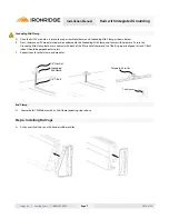
Rail to Rail Expansion Joint
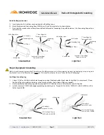
A. Insert splice into first rail then secure splice with self-drilling screw.
B. Attach hardware and Grounding Strap (9AWG) one (1) inch from end of rail as shown below.
C. Next, slide the second rail over the splice and attach other end of Grounding Strap with hardware. (Use Grounding Strap only on
rails with lugs.)
Standard Rail
Light Rail
1/2” Gap
6” inside Rail
Self-drilling screw
Grounding
Strap
1” From Edge (2x)
Torque to 84 in-lbs
Centered 1” From Edge
Torque to 84 in-lbs
1/4” Hex Nut
Grounding Strap
1/4” T-Bolt
1/2” Gap
3” inside Rail
Self-drilling screw
Grounding
Strap
1” From Edge (2x)
Torque to 84 in-lbs
Centered 1” From Edge
Torque to 84 in-lbs
1/4” Hex Nut
Grounding Strap
1/4” T-Bolt
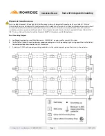
Step 4. Equipment Grounding
Note:
In order to properly ground the PV modules and IronRidge components to the equipment ground, a grounding lug or Lay-in Lug must
be attached to one (1) rail near the end of each row. This connection requires the use of one of the two following lugs.
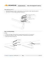
IronRidge Grounding Lug
1. Using a 13/64” or #7 drill bit, drill a hole through one side of the Standard Rail (both sides for Light Rail), a minimum of ½” from
the end of the rail; roughly centered on internal cavity of rail as shown below. (Debur as needed)
2. Next assemble the Grounding Lug with the provided #10-32 Machine Screw, #10 Star Washer and #10 Kep Nut.
3. Install a minimum 10AWG solid copper grounding conducting wire. Torque to 20 in-lbs for 10AWG, 25 in-lbs for 8AWG, or 35 in-
lbs for 4 and 6AWG.
Standard Rail
Light Rail
#10 Kep Nut
Star Washer
#10 Hex Bolt
Torque to 32 in-lbs
#10 Set Screw Torque
to 20 in-lbs for 10AWG
Star Washer
#10 Hex Bolt
Torque to 32 in-lbs
#10 Set Screw Torque
to 20 in-lbs for 10AWG
#10 Kep Nut


