www.ironridge.com | 800-227-9523
© Copyright 2012 IronRidge, Inc. All rights reserved.
2
| Standard Rail Installation Manual
Introduction
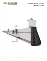
The IronRidge Standard Rail System is a flexible and straightforward roof mounting solution for a wide variety of solar
photo- voltaic (PV) needs. Due to its modular design, it can easily handle a wide variety of panel sizes and quantities.
1. Installer Responsibility
The installer is solely responsible for:
♦
Complying with all applicable local or national building codes, including any that may supersede this manual;
♦
Ensuring that IronRidge and other products are appropriate for the particular installation and the installation
environment;
♦
Ensuring that all structural support members, including the roof, its rafters, and connections, can support the
array under all code level loading conditions;
♦
Using only IronRidge parts and installer-supplied parts as specified by IronRidge. Substitution parts may void
the warranty;
♦
Ensuring that anchoring devices including lag screws have adequate pullout strength and shear capacities as
installed;
♦
Maintaining the waterproof integrity of the structural support or roof, including selection of appropriate flash-
ing;
♦
Ensuring safe installation of all electrical aspects of the PV array; and
♦
Ensuring correct and appropriate design parameters are used in determining the design loading used for the
specific installation. Parameters, such as snow loading, wind speed, exposure and topographic factor should be
confirmed with the local building official or a licensed professional engineer.
2. Customer Support
IronRidge makes every effort to ensure your mounting kit is easy to install. If you need assistance at any point with
your installation or have suggestions on how we can improve your experience, call IronRidge customer support: (707)
459-9523
3. Tools Required For Assembly
The following tools are required to assemble the IronRidge Standard Rail System:
Tool
Use for
Wrenches
Open-end wrench, Box-end wrench, or
socket drive with sockets to support the fol-
lowing size hex heads:
♦
7/16”
♦
9/16”
♦
1/4 cap-end screws and bolts
♦
3/8 cap-end screws and bolts

