background image


www.ironridge.com    |    800-227-9523    

                                       © Copyright 2012 IronRidge, Inc. All rights reserved.

8

  |  Standard Rail Installation Manual

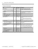
Parts required for this step

Qty

Part Number

Internal Splice

1

29-7000-010

110-16 x1/2” , self-drilling, self tapping screw, SS

8

48-1016-500

WEEB Bond Jumper (if used)

see below 29-4000-003


1. 

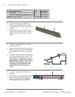
On the next piece of rail, slide 3/8-16”  

bolts into the side facing t-slot on the 

rail. Space the bolts out to match the foot 

spacing.

2. 

On this same piece of rail, slide 1/4-20”  

bolts into the top facing t-slot on the rail. 

Space the bolts out to match the panel 

spacing.

3. 

Lay the rail on its side, with the slotted 

side down as shown. 

4. 

Slide the internal splice half way into the 

internal cavity in the rail. It should extend 

approximately six (6) inches into the cav-

ity. 

5. 

Using two of the self-drilling, self-tapping 

screws, secure the internal splice into the 

rail utilizing the screw pattern shown at 

right.  

(Note- For installations that utilize 

WEEB Bonding Jumpers, please refer to 

Wiley/Burndy installation manual for 

“IronRidge Light and Standard Series 

Rails” for proper installation proce-

dures.)

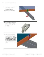
6. 

Loosely mount this piece of rail onto its 

footings.

7. 

By moving this second rail along its foot-

ings, the internal splice should slip into 

the cavity on the first rail, with the rails 

butting tightly and evenly together.

Summary of Contents for Standard Rail Roof Mounting

Page 1: ...Standard Rail Roof Mounting Installation Manual www ironridge com 800 227 9523 Rev B May 2012 This manual s part 91 0700 004 Copyright 2012 IronRidge Inc All rights reserved ...

Page 2: ... that anchoring devices including lag screws have adequate pullout strength and shear capacities as installed Maintaining the waterproof integrity of the structural support or roof including selection of appropriate flash ing Ensuring safe installation of all electrical aspects of the PV array and Ensuring correct and appropriate design parameters are used in determining the design loading used fo...

Page 3: ...e conducted by skilled licensed and bonded electricians All work must comply with all national state and local installation procedures product and safety standards These standards include but are not limited to applicable National Electrical Code NEC National Electrical Installation Standards NEIS UL Standards and OSHA Regulations For installations that utilize WEEBs WEEB Lugs and WEEB Bonding Jum...

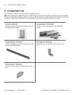
Page 4: ...k the packing list that ships with every mount for a confirmation of the items that are intended to ship with the specific product on your order L Foot 51 6000 002 Attaches to the roof and is the anchor point for the rest of the panel assembly Internal Splice 51 7000 002 Ties the extrusion rails together extending their length Standard Rail 51 7000 XXX Attaches to the foot via the foot clamp and p...

Page 5: ... 7000 xxx Used between PV panels to secure to Stan dard Rail 1 kit will cover 2 PV panels within a row Part number changes depending on panel required Center Clamp 4 51 6000 005 1 4 20 x 2 00 hex cap bolt SS or 1 4 20 x 2 50 hex cap bolt SS or 1 4 20 x 2 75 hex cap bolt SS 4 23 2520 200 23 2520 250 23 2520 275 Length of bolt depends on the thickness of the PV panel 1 4 20 flange nut SS 4 25 2501 0...

Page 6: ...ot 4 51 7000 001 3 8 16 x 1 hex cap bolt SS 4 23 3716 100 3 8 16 flange nut SS 4 25 2501 016 Center Clamp Kit 1 29 7000 xxx 1 4 20 x 2 00 hex cap bolt SS or 1 4 20 x 2 50 hex cap bolt SS or 1 4 20 x 2 75 hex cap bolt SS 4 23 2520 200 23 2520 225 23 2520 250 23 2520 275 End Clamp Kit 1 29 7000 xxx 1 4 20 x 1 SS hex cap bolt SS 4 23 2520 100 1 Mount all of the feet to the roof in the desired locatio...

Page 7: ...n the roof Mount the rail to each foot with a flange nut and hex bolt Hand tighten the nuts and check the level of the rail Tighten 3 8 16 hardware to 180 in lbs Step 2 mounting the next pieces of rail Parts required for this step Qty Part Number Standard Rail 4 51 7000 XXX L Foot Assembly Kit 1 29 7000 017 Foot 4 51 7000 001 3 8 16 x 1 hex cap bolt SS 4 23 3716 100 3 8 16 flange nut SS 4 25 2501 ...

Page 8: ...panel spacing 3 Lay the rail on its side with the slotted side down as shown 4 Slide the internal splice half way into the internal cavity in the rail It should extend approximately six 6 inches into the cav ity 5 Using two of the self drilling self tapping screws secure the internal splice into the rail utilizing the screw pattern shown at right Note For installations that utilize WEEB Bonding Ju...

Page 9: ...epeat this procedure for the remaining rails Step 3 clamping the panels to the rails Parts required for this step Qty Part Number Center Clamp Kit 1 29 7000 xxx 1 4 20 flange nut SS 4 25 2501 014 End Clamp Kit 1 29 7000 xxx 1 4 flange nut SS 4 25 2501 014 WEEB DMC if used see below 29 4000 001 1 Lay the first PV module in posi tion on the rails Note For installations that utilize WEEBs please refe...

Page 10: ...the opposite side of the PV module Assemble the center clamps by putting a clamp on the bolt followed by the flange nut 5 Place the second PV Module into position on the rails sliding it against the first so the center clamps are in contact with the edges of both panels Note For installations that utilize WEEBs please refer to Wiley Burndy in stallation manual for IronRidge Light and Standard Seri...

Page 11: ...e Inc All rights reserved 11 Standard Rail Installation Manual 6 Tighten to 10 ft lbs 120 in lbs 7 Repeat the procedure using center clamps to secure each successive module 8 Secure the last module at the end of the rails using the other set of end clamps ...

Page 12: ...e not followed by Purchaser for IronRidge s galvanized steel based components The warranties above do not cover any parts or materials not manufactured by IronRidge and exclude non functionally related defects as defined solely by IronRidge The warranties do not cover any defect that has not been reported to IronRidge in writing within twenty 20 days after discovery of such defect In the event of ...

Reviews: