www.ironridge.com | 800-227-9523
© Copyright 2012 IronRidge, Inc. All rights reserved.
9
| Standard Rail Installation Manual
8.
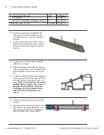
Maintain rail alignment while following
the next steps.
9.
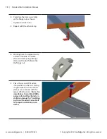
You should mark off approximately six (6)
inches from the end of the first rail (where
the internal splice should end). Drive two
self tapping screws through the first rail in
utilizing the pattern shown at right within
the area you marked off.
10.
Repeat this procedure for the remaining
rails.
Step 3 - clamping the panels to the rails
Parts required for this step
Qty
Part Number
Center Clamp Kit
1
29-7000-xxx
1/4-20 flange nut, SS
4
25-2501-014
End Clamp Kit
1
29-7000-xxx
1/4 flange nut, SS
4
25-2501-014
WEEB-DMC (if used)
see below 29-4000-001
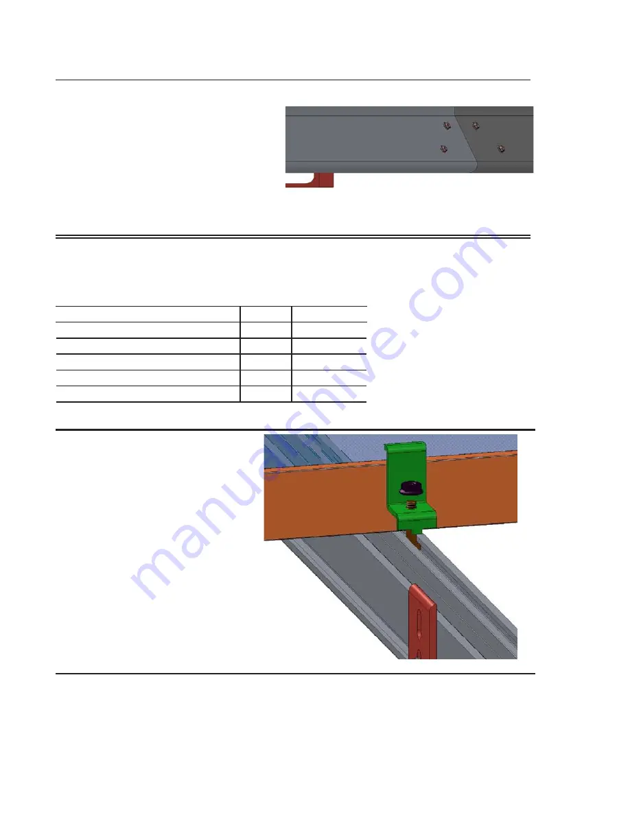
1.
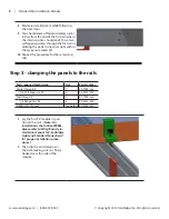
Lay the first PV module in posi-
tion on the rails.
(Note- For
installations that utilize WEEBs,
please refer to Wiley/Burndy in-
stallation manual for “IronRidge
Light and Standard Series Rails”
for proper installation proce-
dures.)
1.
Then slip the end clamp over
the bolt, making sure it is firmly
hooked over the side of the
module.

