Solar Mounting Made Simple
R
Light Rail
Installation Manual
Page 5
2013 v1.3
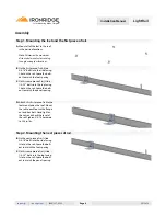
C.
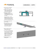
Lay the rail on its side, with the
slotted side down as shown.
D.
Slide the internal splice half way
into the internal cavity in the rail.
It should extend approximately
three (3) inches into the cavity.
F.
Loosely mount this piece of rail
onto its footings.
G.
By moving this second rail along
its footings, the internal splice
should slip into the cavity on the
first rail, with the rails butting
tightly and evenly together.
H.
Maintain rail alignment while
following the next steps.
I.
You should mark off approximately
three (3) inches from the end of the
first rail (where the internal splice
should end). Drive one (1) self-
tapping screws through the second
rail, one (1”) inch from the edge
utilizing the same horizontal
location as the first rail.
E.
Using one (1) self-drilling,
self-tapping screw, one (1”) inch
from the edge of the rail, secure the
internal splice into the rail as shown
on the right.
Note: For installations that utilize
WEEB Bonding Jumpers, please refer to
Wiley/Burndy installation manual for
“IronRidge Light and Standard Series
Rails” for proper installation procedures.
J.
Repeat this procedure for the
remaining rails.

