Kwik-Way
SVS II Deluxe Valve Refacer
Copyright © 2018 by Irontite Products Inc.
All Rights Reserved. Rev. 180802
pg. 11
SETTING SPINDLE SLIDE STOPS
This machine is equipped with adjustable stops to limit the travel of the grinding wheel spindle slide.
These stops, when set, prevent the wheel from striking the chuck or the valve stem.
1. With the valve installed in the chuck, all motors off, and the thumbscrews loose, advance the
traverse handle to the left.
2. Feed valve up to valve wheel.
3. Be sure the grinding wheel does not strike either the chuck or the valve stem.
4. Slide the right hand adjustable stop up against the fixed stop and tighten thumb screw.
CONTROLS AND SWITCHES
Before attempting to operate this machine, first familiarize yourself with all controls and switches and
the functions of each.
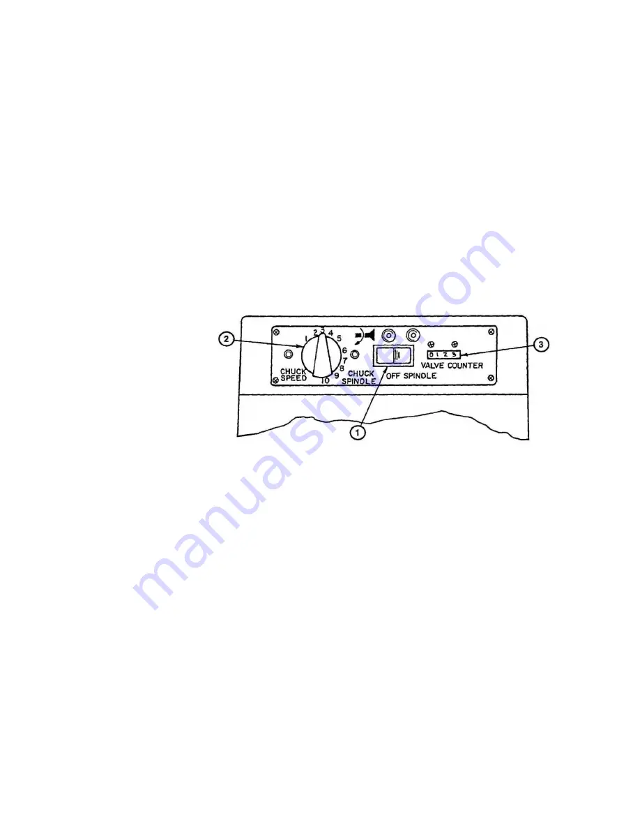
MAIN SWITCH (Item 1, Figure 2 below)
This switch has three positions. In the left position, both the spindle and the chuck motor are on. With
the switch in the right position, only the spindle motor will run. When centered, both chuck and spindle
motors are off.
CHUCK SPEED CONTOLLERS (Item 2, Figure 2 above)
Your SVSII Deluxe Valve Facer is equipped with a variable speed chuck motor, which allows you to
alter the rotational speed based on the valve head diameter (See chart on chuck cover).
SPINDLE SLIDE SWITCH
This machine is equipped with an automatic switch, which shuts off the spindle (grinding) motor, chuck
motor and the coolant pump when the traverse handle (Item 3, Figure 4) is in the far right position.
VALVE COUNTER (Item 3, Figure 2)
This machine is equipped with an automatic valve counter enabling you to keep an accurate count of
valve facing production.
Figure 2


