background image

Page 7 of 18 


DO NOT MODIFY THE PROVIDED PLUG. If it will not fit the receptacle, have the proper 
receptacle installed by a qualified electrician. 


CHECK with a qualified electrician or service person if you do not completely understand the 
grounding instructions, or if you are not sure the tool is properly grounded. 

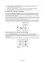
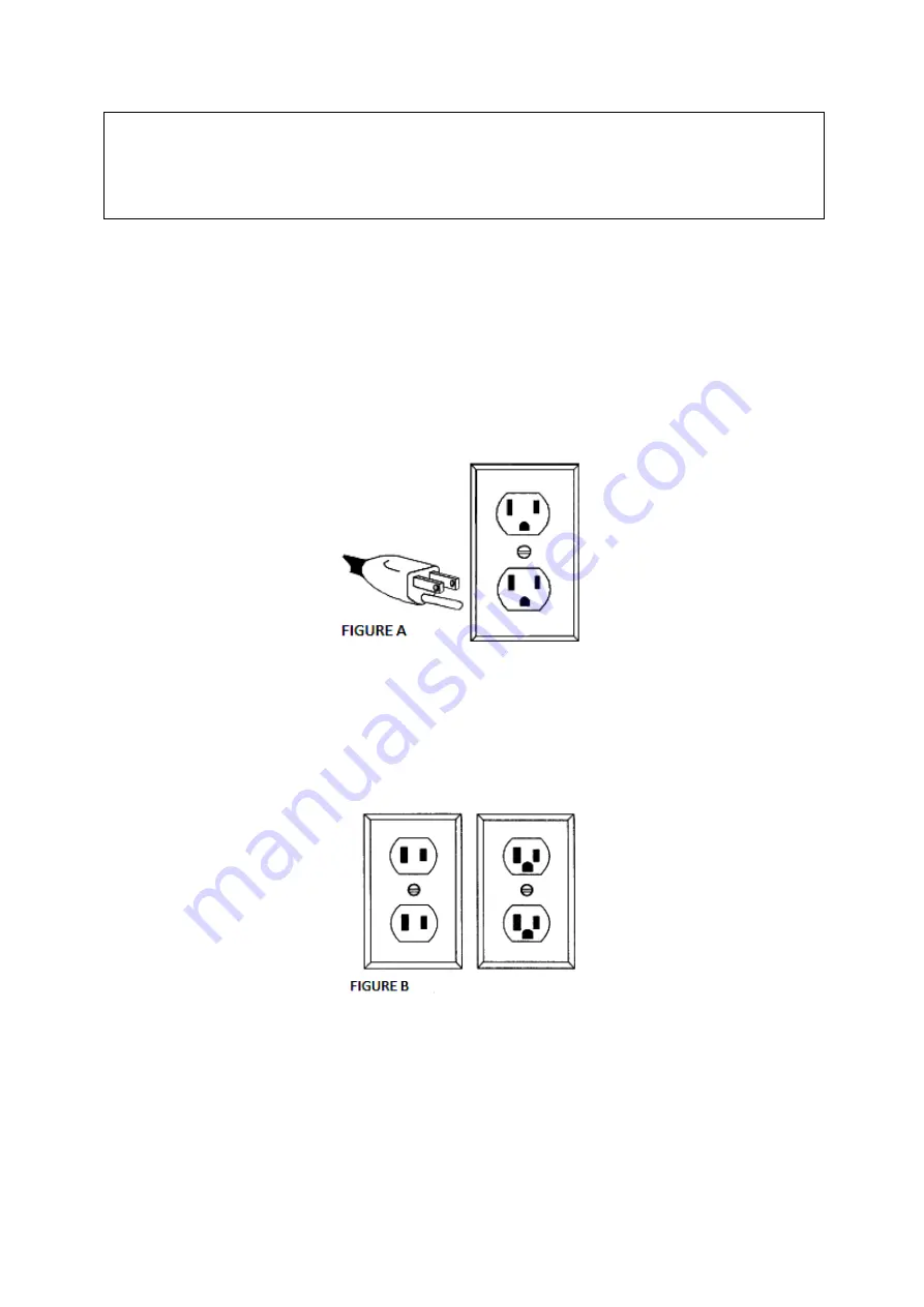
Grounded Tools: Tools with 3-Prong Plugs 

Tools marked with 

Grounding required

 have a 3-wire cord and 3-prong grounding plug. The plug 

must be connected to a properly grounded outlet. If the tool should electrically malfunction or break 
down, grounding provides a low resistance path to carry electricity away from the user, reducing the 
risk of electric shock. (See Figure A.) 

The grounding prong in the plug is connected through the green wire inside the cord to the grounding 
system in the tool. The green wire in the cord must be the only wire connected to the tool’s grounding 
system and must never be attached to an electrically live terminal.  

Your tool must be plugged into an appropriate outlet, properly installed and grounded in accordance 
with all codes and ordinances. The plug and outlet should look like those in the following illustration.  


Double Insulated Tools: Tools with Two-Prong Plugs 

Tools marked 

Double Insulated

 do not require grounding. They have a special double insulation 

system which satisfies OSHA requirements and complies with the applicable standards of 
Underwriters Laboratories, Inc., the Canadian Standard Association, and the National Electrical Code. 
(See Figure B.) 

Double insulated tools may be used in either of the 120 volt outlets shown in the following illustration.  


Summary of Contents for 61527

Page 1: ...Drain Cleaner Owner s Manual WARNING Read carefully and understand all ASSEMBLY AND OPERATION INSTRUCTIONS before operating Failure to follow the safety rules and other basic safety precautions may re...

Page 2: ...that you read the entire manual to become familiar with this product before you begin using it This drain cleaner is designed for certain applications only Northern Tool and Equipment is not responsib...

Page 3: ...t Safety Information 4 Specific Operation Warnings 6 Grounding 6 Extension Cords 8 Main Parts of Drain Cleaner 9 Before Each Use 9 Operating Instructions 10 After Each Use 12 Maintenance 13 Troublesho...

Page 4: ...are specific applications for which the product was designed Use the right tool for the job DO NOT attempt to force small equipment to do the work of larger industrial equipment There are certain app...

Page 5: ...pply or turning on the tool A wrench or key that is left attached to a rotating part of the tool may cause personal injury Secure the work with clamps or a vise instead of your hand when practical Thi...

Page 6: ...pipe use the front guide tube If the distance is too long it may cause winding or it may break off of the flexible shaft Do not operate the drain cleaner while reversing pressing the forward and rever...

Page 7: ...g in the plug is connected through the green wire inside the cord to the grounding system in the tool The green wire in the cord must be the only wire connected to the tool s grounding system and must...

Page 8: ...e smaller the wire s gauge number the greater the capacity of the cord For example a 14 gauge cord can carry a higher current than a 16 gauge cord Minimum extension cord wire size is shown in the foll...

Page 9: ...are no damaged machine parts that may pose a threat to your safety Lubricate the flexible shaft according to this manual Check to be sure the flexible shaft is not worn or damaged If it is immediatel...

Page 10: ...operate the drain cleaner while reversing pressing the forward and reverse rotation button R Operating in the R state can cause damage to the flexible shaft The button R is only used to exit the flexi...

Page 11: ...forward to the F position and the flexible shaft will move forward 3 Press the speed switch lightly and pull the handle back to the R position The flexible shaft will retract 1 When the forward and r...

Page 12: ...ws with an Allen wrench not included and remove the unwanted flexible shaft 4 Insert the new flexible shaft into the connector align the screw holes and tighten the M4 set screws again 5 Push the flex...

Page 13: ...sed Keep your tool in good repair Keep handles dry clean and free from oil and grease The following chart is based on a normal operation schedule Maintenance Interval Maintenance Point Daily before op...

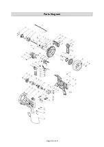
Page 14: ...Page 14 of 18 Parts Diagram...

Page 15: ...lve 1 20 Drum 1 21 O Seal ring 1 22 Waterproof plug 1 23 Screw M6 60 1 24 Flash washer 1 25 Left cover 1 26 Locating plate 1 27 Screw M6 16 6 28 Bearing 606 6 29 Bearing base 1 30 Spring 6 22 2 31 Ste...

Page 16: ...l product components are available for replacement The illustrations provided are a convenient reference to the location and position of parts in the assembly sequence When ordering parts the followin...

Page 17: ...claim contact Us at 1 800 222 5381 identify the product by make and model number and follow the claim instructions that will be provided The product and the purchase receipt must be provided to Us in...

Page 18: ...Page 18 of 18 Distributed by Northern Tool Equipment Company Inc Burnsville Minnesota 55306 www northerntool com Made in China...

Reviews: