background image

Ironwood BR23  |  User Manual

11

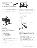
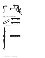
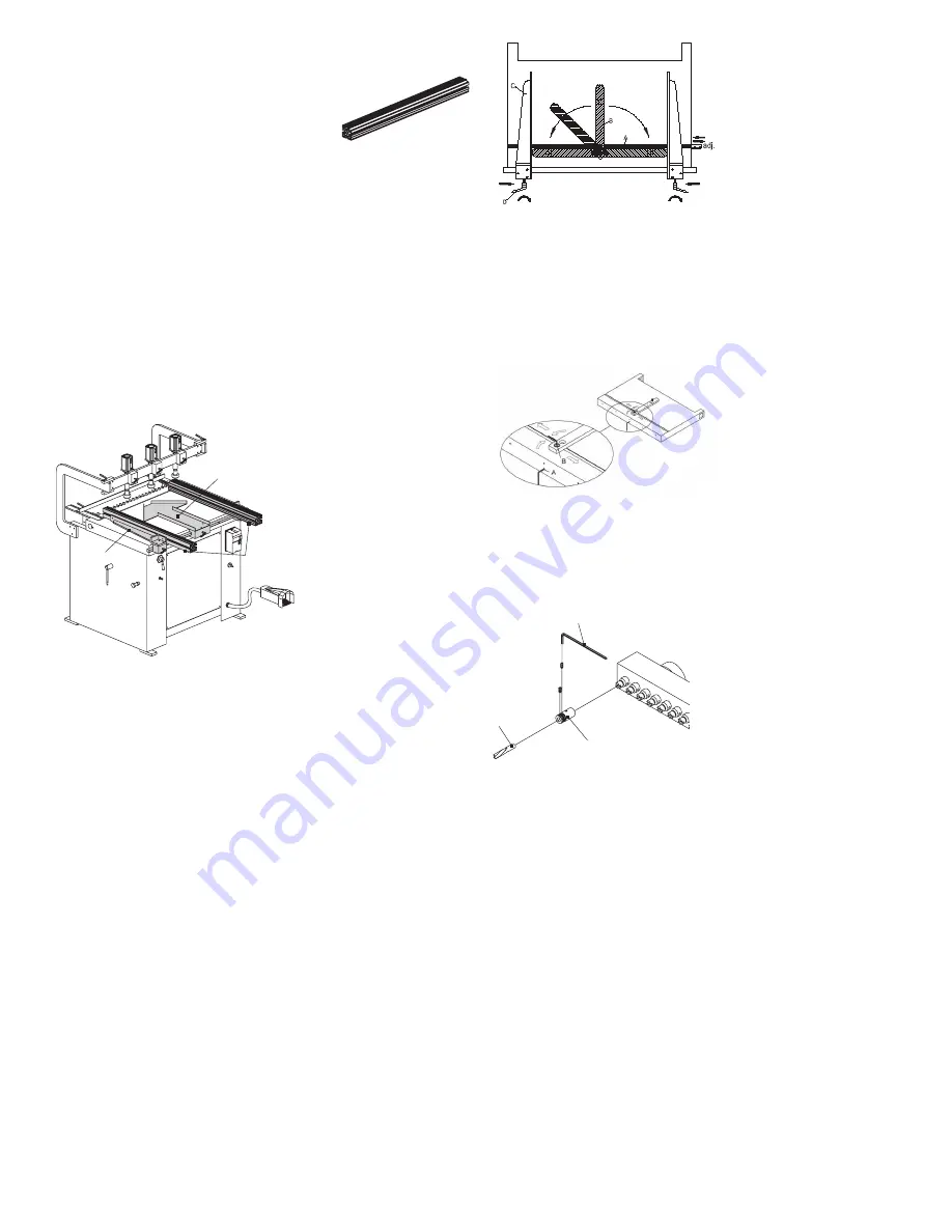
4.2 Left- and Right-Side Fences 

PARTS REQUIRED:

•  2 side fence sections
•  2 side fence housings (1 left, 1 right)

Right- and left-side fences are easily added or removed to 
accommodate various applications. 

To assemble:

1.  Slide the side fence housing onto steel guide rail mounted on 

the front of the machine table.

2.  Slide the side fence onto alignment blocks on the side fence 

housing.

3.  Lock the side fence to secure it to the fence housing.

4.  Move the side fence to desired position.

5.  Lock in place.

Repeat steps for the opposite side fence.

45° Fence assembly

Left and
right side
fences

Side fence housing

4.3 45º fence

PARTS REQUIRED: 

•  1 45º fence assembly

The 45º fence assembly is easily added or removed to 
accommodate 45º parts.  

To assemble:

1.  Remove the side fences.

2.  Slide the 45º fence into position.

3.  Lock the 45º fence in place.

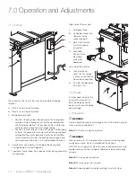
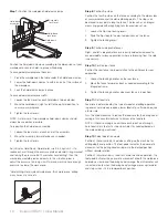
4.4 The Mirror-Image Device

1.  Calibrate the zero point of rule (A) to the middle of the mirror-

image device (B).

2.  Turn the device (B) left/right side to adjust the length user 

needs. (Either left or right side first is ok.)

3.  Move the Fene LH (C) to touch the top of device (B) to get the 

correct distance.

4.  Lock the lever (D) to fix the correct distance.

5.  Repeat steps 3-4 to adjust the length of another side.

Zero-point adjustment - The zero-point has been set by factory 
before shipment. Please do not adjust the zero-point (screw A), if not 
necessary.

Loosen the screw (A) with 1-2 turns. Loosen the screw (B) with 1-2 
turns and adjust mirror-imaging advice to zero-point. Tighten screws 
(A) and (B) when the desired zero-point is obtained.

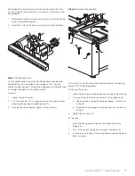
4.5 Drill Bits 

PARTS 

REQUIRED:          TOOLS 

REQUIRED:

•  Drill bit quick chucks (supplied)   •  Hex Allen wrench 
•  Drill bits (not supplied)

1.  Determine which drill bit locations will be used to accommodate 

the application. 

NOTE: Each spindle is colored red or black based on rotation 
direction (left or right). Please observe the rotation direction when 
selecting tooling for each spindle.

2.  Carefully insert a drill bit quick chuck into the spindle in the 

desired positions. Make sure the pin inside the quick chuck is 
engaged with the notch on the spindle.

3.  Install drill bits into the other quick chucks in the same manner. 

4.  Tighten the two set screws with an Allen wrench.

5.  Make sure the bits are aligned and all at the same height. 

Remove and reinstall any out-of-alignment drill bits so that all 
are aligned. 

Remove Drill Bits

To remove a drill bit quick chuck (with drill bit) from the spindle, 
slightly turn the quick chuck to the left and pull up.

Hex Allen wrench

Drill bit

Drill bit quick chuck


Summary of Contents for BR23

Page 1: ...nd adjustments controls operation applications maintenance cleaning troubleshooting safety connect to power delivery and installation inspection pre operation cleaning assembly ream extension fence an...

Page 2: ...let 3 6 Level 3 7 Pre Operation Cleaning 4 0 Assembly 10 4 1 Ream Extension Fence and Stops 4 2 Left and Right Side Fences 4 3 45 Fence 4 4 The Mirror Image Device 4 5 Drill Bits 5 0 Connect to Power...

Page 3: ...ite www stilesmachinery com ironwood br 23 Machine Model_____________________________________________ Machine Serial Number______________________________________ 1 3 Features Three Quick Release pneum...

Page 4: ...ance between spindles 32mm Number of pneumatic clamps 3 Working space requirement w o extension fence 41 x 59 x 53 1040mm x 1510mm x 1350mm Dimensions of working table 215 8 x 37 550mm x 950mm Working...

Page 5: ...ctrical shock LABEL NO 1 LABEL NO 2 LABEL NO 3 WARNING Never use the BR23 for purposes other than its intended use Do not modify or remove any guards or other safety features Improper use or modificat...

Page 6: ...st connect the BR23 to the building power source Do not use extension cords Be sure that the electrical current of the power source is of the same characteristics as the 230 volt electrical system sup...

Page 7: ...department The machine will arrive fully crated and secured to a pallet Use a hand truck or fork lift to move the machine on its pallet as close to its final position as possible If you do not intend...

Page 8: ...your equipment you should inventory its parts Open and check the contents of all containers to ensure all tools hardware and accessories are included The tool kit should contain the following items 1...

Page 9: ...le wrench Use a bubble level along the length and width of the tabletop surface to check for level Use an adjustable wrench to adjust leveling bolts to level the machine Be sure to level the machine 3...

Page 10: ...o assemble 1 Insert a connection rod halfway into the center hole at each end of the center back fence 2 Insert a connection bar into the T slot at each end of the center back fence leave approximatel...

Page 11: ...he correct distance 5 Repeat steps 3 4 to adjust the length of another side Zero point adjustment The zero point has been set by factory before shipment Please do not adjust the zero point screw A if...

Page 12: ...cables through opening of terminal box 4 Connect the two power cables to terminals L1 and L2 and the yellow green ground wire to ground terminal 5 Replace the clear plastic insulator and the power bo...

Page 13: ...e is properly grounded Follow the grounding procedure indicated by the National Electric Code and local regulating authorities GUARDS Make certain that machine guards are in place and in good working...

Page 14: ...t which boring head drills into workpiece Right side of the machine A Emergency Stop B Air Supply Connection Compressed air connection point C Main On Off Switch Turns main power on and off D Foot Ped...

Page 15: ...the crank lever C to change position of the boring head observing the position on digital readout D 3 Once positioned as desired tighten the lock lever A Step 6 Set angle of boring head B C A D The s...

Page 16: ...oved to any point along the fence The fence has an integral measuring guide with magnifying lens for precision set up 1 Loosen the flip stop locking levers 2 Slide the flip stops to the desired positi...

Page 17: ...The workpiece must sit flat on the table without rocking Dust created by manufacturing activities may be harmful to your health Your risks from exposure may vary Always work in a well ventilated area...

Page 18: ...Ironwood BR23 User Manual 18 Joining at 0 90 Compound Machining Line Boring on Long Panel Using Extension Bar Boring for Hinge Installation...

Page 19: ...bricate the boring head using a grease gun and a non melting moly grease Apply no more than 6 grease gun strokes Spindle bearings are permanently lubricated and require no further lubrication Spindle...

Page 20: ...no air leaking among pipes Drills are burning wood Drill feed speed too fast Drill feed speed too low Dull tooling Improper tooling Slow down feed speed Speed up feed speed Sharpen or replace tooling...

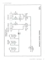
Page 21: ...Ironwood BR23 User Manual 21 9 1 Air Circuit Diagram...

Page 22: ...Ironwood BR23 User Manual 22 9 2 Electrical Diagram...

Page 23: ......

Page 24: ...Stiles Machinery Inc 3965 44th St SE Grand Rapids MI 49512 p 616 698 7500 f 616 698 9411 www stilesmachinery com 2013 Stiles Machinery Inc Version A November 2013...

Reviews: