Ironwood BR23 | User Manual
14
7.0 Operation and Adjustments
7.1 Controls
A
B
D
E
C
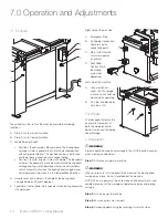
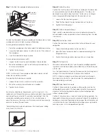
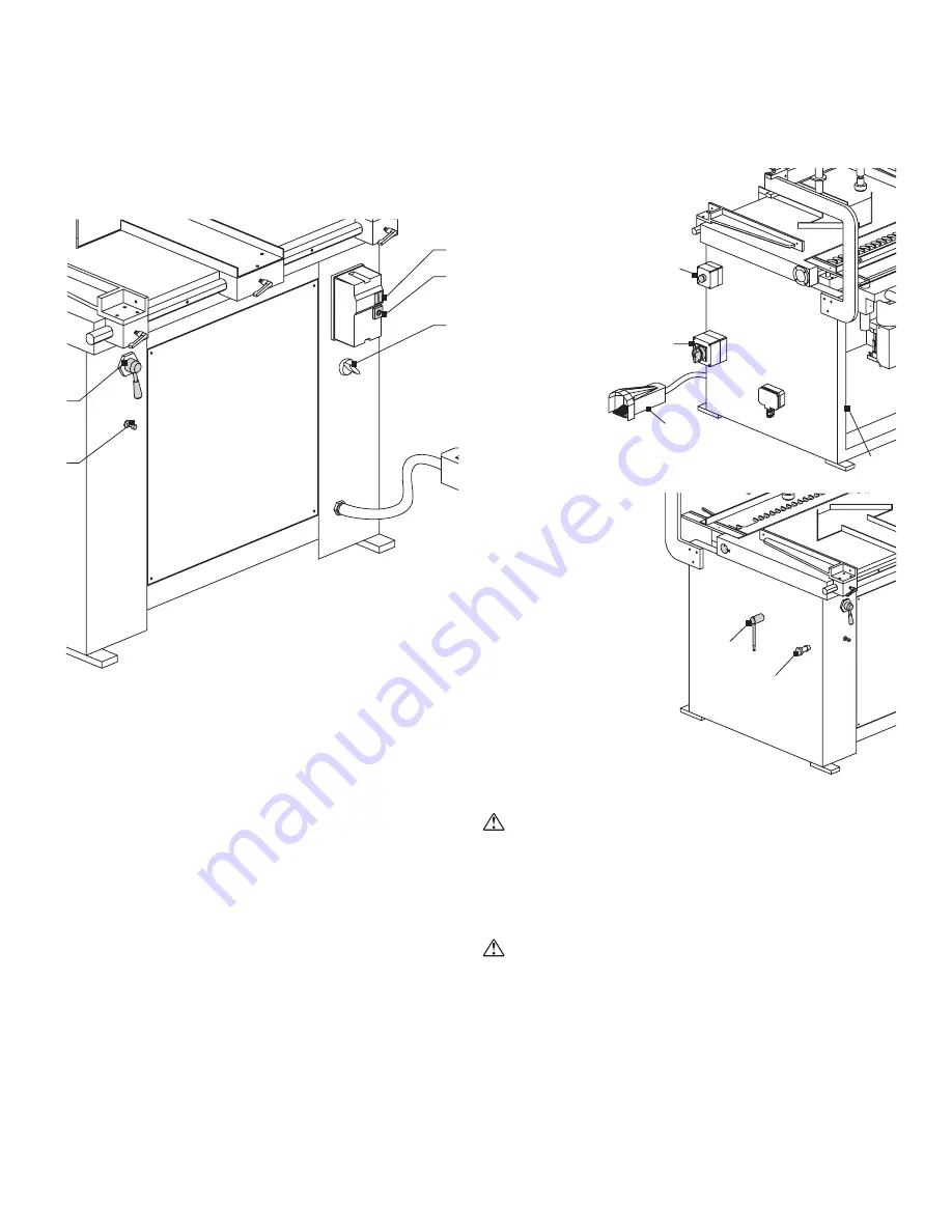
The controls on the front of the machine provide the following
functions:
A. Start: Push to start drill rotation.
B. Stop: Push to stop drill rotation.
C. Mode Selector Switch
• Position 1 (hand symbol): Manual mode. The boring head
carriage will move pneumatically into the desired position
without spindle rotation. This position can be used to raise
and lower boring head to easily change tooling.
• Position 2 (circular arrows): Automatic mode. The foot pedal
activates the pneumatic movement of both the boring head
carriage and the work hold-down clamp; the drill spindles
will run automatically when the boring head carriage moves
up/forward and stop when it is in a lowered/back position.
D. Handle Lever Valve: Adjusts the angle of the boring head
carriage between 90 and 0 degrees.
E. Feed Rate Control Knob: Sets speed at which boring head drills
into workpiece
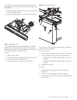
Right side of the machine:
A. Emergency Stop
B. Air Supply Connection:
Compressed air
connection point.
C. Main On/Off Switch:
Turns main power
on and off.
D. Foot Pedal
Control: Starts
the drilling
cycle when
depressed.
Left side of the machine:
A. Lock mechanism:
Locks the tilt carriage
in place so it cannot be
moved when operating.
B. 45º stop: Enables quick
tilt setup at 45º.
Foot Pedal
The foot pedal activates the
pneumatic movement of
both the workpiece hold-
down clamps and the boring
head carriage.
7.2 Operation
WaRninG
Always keep the boring head carriage in the LOCK position, except
when making an adjustment.
Step 1:
Activate air supply to machine
WaRninG
When air pressure is first applied to the machine, the boring head
carriage may move. Do not stand behind the machine.
NOTE: The air supply must be on to make certain adjustments and
enable movement of the workpiece hold-down clamps and boring
carriage.
Step 2:
Turn on power to machine
Step 3:
Ensure air pressure is correct
Step 4:
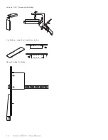
Set boring depth using the revolving turret with stops
A
C
B
D
A
B


