Ironwood BR23 | User Manual
16
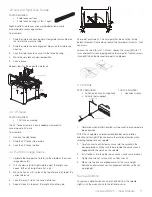
Step 7:
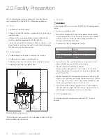
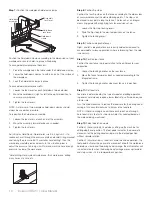
Position the workpiece hold-down clamps
Hold-down
clamp
Hold-down
assembly
Assembly
lock lever
Hold-down
lock lever
Position the hold-down clamps according to the dimensions of your
workpiece to securely hold it in place while boring.
To accommodate workpiece thickness:
1. Place the workpiece on the table under the hold-down clamps.
2. Lower the hold-down clamps to within an inch of the surface of
the workpiece.
3. Lock the hold-down clamps in place.
To accommodate workpiece width:
1. Loosen the lock lever for each hold-down to be adjusted.
2. Move the hold-down(s) right or left to the optimal position to
secure your workpiece.
3. Tighten the lock levers.
NOTE: A minimum of two workpiece hold-down clamps should
always be used when possible.
To reposition the hold-down assembly:
1. Loosen the lock levers at each end of the assembly.
2. Move the assembly forward or back as needed.
3. Tighten the lock levers.
Adj Valve for Hold-Down: Normal pressure 3.5-4 kgs/cm2 is to
reduce exhaust through the pressure plate and avoid O-ring cracked
and licking the pressure. But if user takes hard drilling*, then the
work piece would be removed easily. In this situation, please
adjust the pressure to 5-6 kgs/cm2 to make machine have enough
pressure to clamp the work piece.
*Hard drilling: Hard material work piece, thick work piece, drilling
many holes at a time, etc.
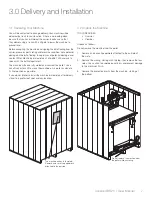
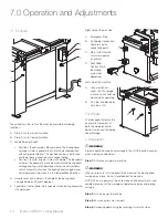
Step 8:
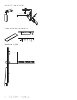
Position flip stops
Position the four flip stops on the fence according to the dimensions
of your workpiece and the desired boring points. The stops can
be moved to any point along the fence. The fence has an integral
measuring guide with magnifying lens for precision set-up.
1. Loosen the flip stop locking levers.
2. Slide the flip stops to the desired positions on the fence.
3. Tighten the locking levers.
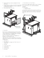
Step 9:
Position side profile fences
Right- and left-side profile fences are easily added or removed to
accommodate various applications where referencing from the side
is necessary.
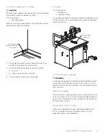
Step 10:
Position rear fence
Position the rear fence in proper relation to the drill block for your
application.
1. Loosen the locking handles on the rear fence.
2. Move the fence forward or back as needed according to the
integrated scale.
3. Tighten the locking handles when rear fence is in position.
Step 11:
Set feed rate
Feed rate is determined by the type of wood and drilling operation.
In general, hard woods require a lower feed rate; soft woods require
a faster rate.
Turn the knob clockwise to reduce the feed rate for the boring head
carriage. Turn counterclockwise to increase the feed rate.
NOTE: If there is burning on a drill hole or chip out on a through-
hole, feed rate is too fast or too slow. Adjust as needed based on
the material being machined.
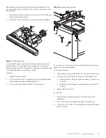
Step 12:
Select operation mode
Position 1 (hand symbol): Used when setting up the machine for
drilling depth and position. The foot pedal activates the pneumatic
movement of the boring head carriage into the desired position
without spindle rotation.
Position 2 (circular arrows): Used for normal machine operation. The
foot pedal activates the pneumatic movement of both the workpiece
hold-down clamp and the boring head carriage; the drill spindles will
run automatically when the boring head carriage moves up/forward
and stops when it is in a lowered/back position.

