Ironwood DBR50 | User Manual
10
4.0 Assembly
To be assembled:
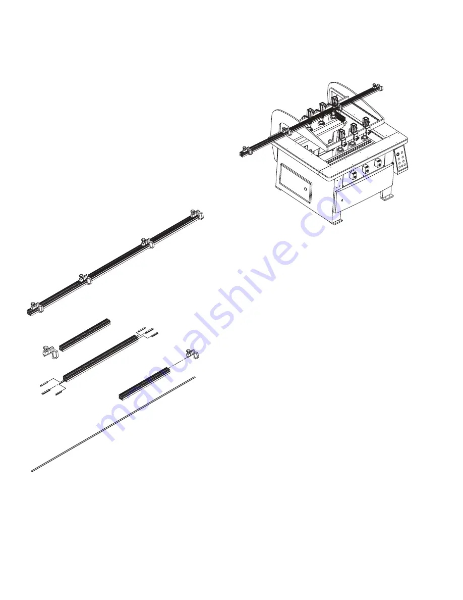
• Rear extension fence and stops
• Drill bits
4.1 Extension Fence and Stops
PARTS REQUIRED:
• 3 fence sections
• 2 connection rods
• 4 connection bars
• 4 flip stops
• 1 measurement tape
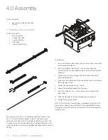
The rear aluminum fence is assembled using three sections: one
49 ¼" (1250mm) section between two 34 ½" (875mm) fence
extensions attached to the left and right of the center section. The
aluminum fence has one beveled corner. The beveled corner is the
mounting slot for the ruler and should be positioned forward for easy
viewing.
To assemble:
1. Insert a connection rod halfway into the center hole at each end
of the center back fence.
2. Insert a connection bar into the T-slot at each end of the
center back fence; leave approximately half the connection bar
exposed.
3. Tighten two set screws through the center back fence onto
each connection bar.
4. Attach the two side fences to the connection rod at each end of
the center back fence.
5. Tighten the connection bar set screws.
6. Loosen the locking handle on the flip stops.
7. Insert flip stops into the t-slot on the aluminum profile of the
back fence.
8. Slide the flip stops to the desired positions on the fence.
9. Tighten the locking handles.
NOTE: A 3-meter measurement tape is included in the tool kit. The
measurement tape can be mounted on the assembled back fence
to provide accurate flip stop measurements over the entire length of
the back fence.
Summary of Contents for DBR50
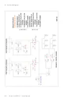
Page 20: ...Ironwood DBR50 User Manual 20 9 1 Air Circuit Diagram...
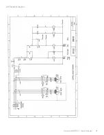
Page 21: ...Ironwood DBR50 User Manual 21 9 2 Electrical Diagram...
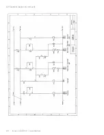
Page 22: ...Ironwood DBR50 User Manual 22 9 2 Electrical Diagram Continued...
Page 23: ...Ironwood DBR50 User Manual 23 9 2 Electrical Diagram Continued...
Page 24: ...Ironwood DBR50 User Manual 24 9 2 Electrical Diagram Continued...
Page 25: ......

