Ironwood DBR50 | User Manual
12
5.0 Connect to Power and Air
5.1 Power connection
• Voltage – Steady state v/- 10% of nominal voltage.
• Machine needs steady voltage at all times.
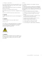
WaRninG
Before connecting power to the machine, make sure all screws and
fasteners are tightened and all mechanical functions work freely.
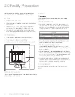
WaRninG
A licensed electrician must complete all connections to electrical
power.
Before connecting to a power source, confirm that the electrical
current of the power source is the same as the electrical system
supplied with your machine. Ensure the machine is protected with
an external over current protective device per your local regulating
authorities.
Machine must be properly grounded to prevent electric shock.
Never connect the yellow/green wire to a live terminal.
Once connected to power source, terminals are electrified even
while the power switch is off.
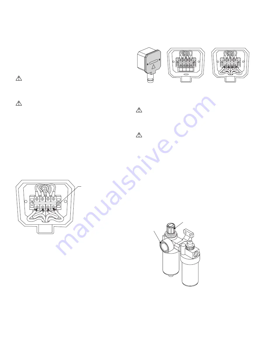
Proper wiring inside
the terminal strip box
L3
2
3
4
L2
L1
PE
PE
L1
L2
1
L3
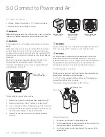
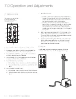
To connect power source to the machine:
1. Remove two screws (A) and remove terminal box cover (B).
2. Remove clear plastic insulator that covers the terminals (C).
3. Insert source power cables through opening of terminal box (D).
4. Connect the two power cables to terminals L1 and L2, (E) and
the yellow/green ground wire to ground terminal (F).
5. Replace the clear plastic insulator (C) and the power box
cover (B).
Remove terminal
box covers
Connect power and
grounding wires
Remove the clear
plastic insulator
that covers the
terminals
L3
2
3
4
L2
L1
PE
P
E
L1
L2
1
L3
L3
2
3
4
L2
L1
PE
P
E
L1
L2
1
L3
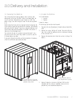
WaRninG
Always shut off power at source before removing terminal box cover.
Failure to comply with this action may result in electric shock.
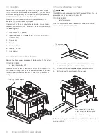
WaRninG
We have covered some basic electrical requirements for the safe
installation of your machine. These requirements may not cover all
installation requirements. You must confirm that your particular electrical
configuration complies with all local codes. Ensure compliance by
checking with your local municipality and a licensed electrician.
5.2 Air Supply Connection
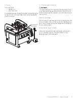
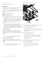
Boring carriage adjustment and Quick-Release clamp operation are
pneumatically controlled using the foot pedal.
A ¼" N.P.T. inlet is supplied with the machine’s air fitter/regulator to
connect the machine to the air supply.
The air pressure regulator should be set to 90-100 psi.
Regulating knob
Pressure gauge
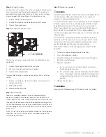
To adjust the pressure:
1. Pull up on the outer ring of the regulating knob.
2. Turn the regulating knob counterclockwise to let air exhaust to a
pressure level below the desired setting.
3. Turn the knob clockwise to slowly increase the pressure to the
desired setting.
Summary of Contents for DBR50
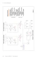
Page 20: ...Ironwood DBR50 User Manual 20 9 1 Air Circuit Diagram...
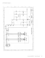
Page 21: ...Ironwood DBR50 User Manual 21 9 2 Electrical Diagram...
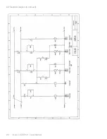
Page 22: ...Ironwood DBR50 User Manual 22 9 2 Electrical Diagram Continued...
Page 23: ...Ironwood DBR50 User Manual 23 9 2 Electrical Diagram Continued...
Page 24: ...Ironwood DBR50 User Manual 24 9 2 Electrical Diagram Continued...
Page 25: ......

