Ironwood DBR50 | User Manual
14
7.0 Operation and Adjustments
7.1 Machine Controls
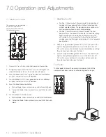
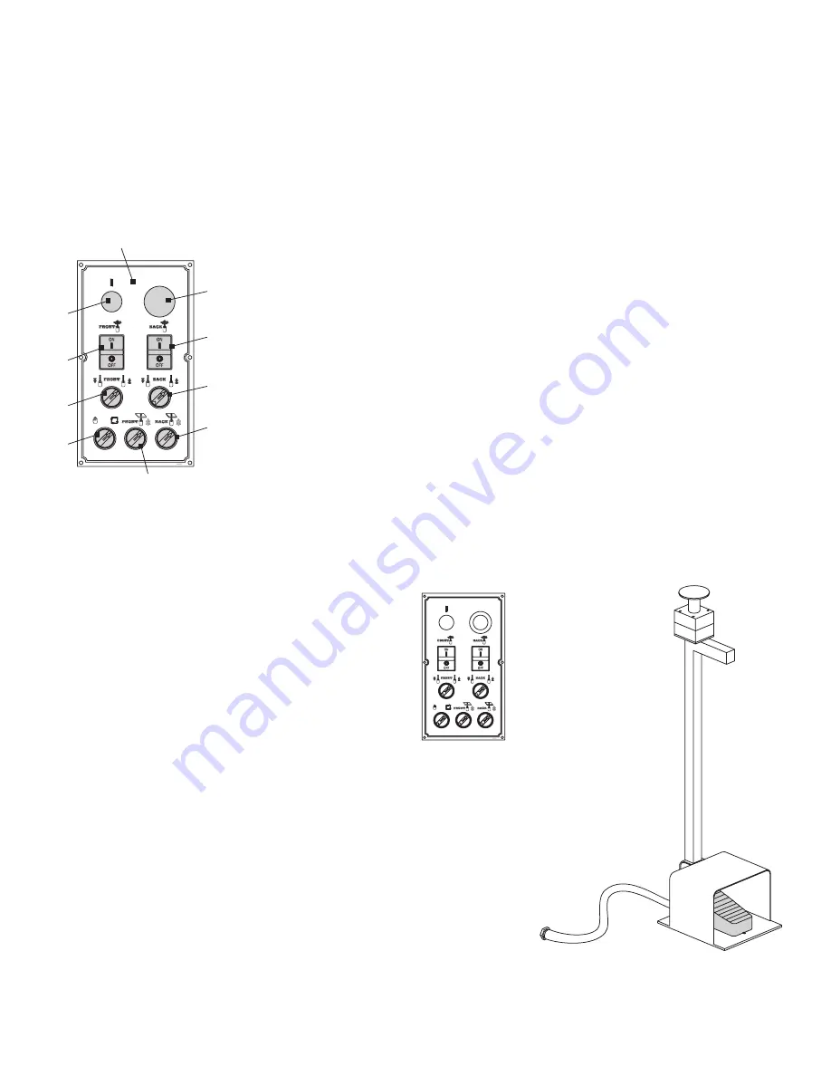
The control unit on the front-right
of the machine pivots for
convenient use and controls
the following functions:
2
4
6
9
8
7
5
3
1
1. Power On: Press to turn on control power to the machine.
2. Emergency Stop/Power Off: Press in case of emergency to
stop drill rotation or to turn off machine control power.
3. Rear Drill Block On/Off: Press green button to turn drill block
on; press red button to turn off drill block.
4. Front Drill Block On/Off: Press green button to turn drill block
on; press red button to turn off drill block.
5. Rear Drill Block Activation Switch:
a. Manual Mode: Allows manual rise and fall of rear drill block
b. Automatic Mode: Allows automatic rise and fall of rear drill
block
6. Front Drill Block Activation Switch:
a. Manual Mode: Allows manual rise and fall of front drill block
b. Automatic Mode: Allows automatic rise and fall of front drill
block
7. Mode Selector switch
• Position 1 (hand symbol): Manual mode. The boring head
carriage will move pneumatically into the desired position
without spindle rotation. This position can be used to raise
and lower boring head to easily change tooling.
• Position 2 (circular arrows): Automatic mode. The foot
pedal activates the pneumatic movement of both the boring
head carriage and the workpiece hold-down clamp; the
drill spindles will run automatically when the boring head
carriage moves up/forward and stop when it is in a lowered/
back position.
8. Back Through-hole Boring Brake On/Off: Turn the knob to the
right for through-hole applications; turn to the left to turn off.
The switch causes the drill bank to slow down before punching
through top of panel to prevent chipout.
9. Front Through-hole Boring Brake On/Off: Turn the knob to the
right for through-hole applications; turn to the left to turn off.
The switch causes drill bank to slow down before punching
through top of panel to prevent chipout.
Foot Pedal
The foot pedal activates the pneumatic movement of both the
workpiece hold-down clamps and the boring head carriages.
Summary of Contents for DBR50
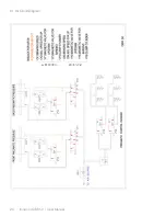
Page 20: ...Ironwood DBR50 User Manual 20 9 1 Air Circuit Diagram...
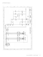
Page 21: ...Ironwood DBR50 User Manual 21 9 2 Electrical Diagram...
Page 22: ...Ironwood DBR50 User Manual 22 9 2 Electrical Diagram Continued...
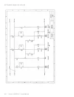
Page 23: ...Ironwood DBR50 User Manual 23 9 2 Electrical Diagram Continued...
Page 24: ...Ironwood DBR50 User Manual 24 9 2 Electrical Diagram Continued...
Page 25: ......

