Ironwood DBR50 | User Manual
16
7.2 Machine Operation
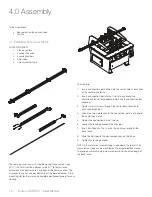
Step 1:
Activate air supply to machine
WaRninG
When air pressure is first applied to the machine, the boring head
carriage may move. Do not stand behind the machine.
NOTE: The air supply must be on to make certain adjustments and
enable movement of the workpiece hold-down clamps and boring
carriage.
Step 2:
Turn on power to machine
Step 3:
Ensure air pressure is correct
Step 4:
Select operation mode
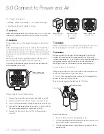
There are two operation modes available on the DBR50 machine.
Manual Mode (hand symbol): Use for manual setup of the machine.
Turn the knob to the left for manual control. The boring head
carriage will move pneumatically into the desired position without
spindle rotation, unless spindle rotation is manually turned on.
Automatic Mode (circular arrows): Use for normal machine
operation.
Turn the knob to the right for automatic up/down movement
of the boring head carriages. The foot pedal activates the
pneumatic movement of both the boring head carriages and the
work hold-down clamp. The drill spindles will run automatically
when the boring head carriages move up and stop when they are
in a lowered position.
Step 5:
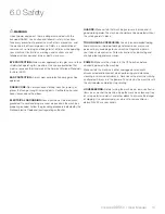
Set boring depth
Attach the crank handle to the left or right digital readout to set
the boring depth for the back and front carriages. The depths are
displayed in millimeters (mm) on the integral digital readouts for both
controls.
To adjust:
1. Turn the crank handle to change position of boring depth,
observing position on digital readout.
Step 6:
Position rear boring head
The rear boring head can be adjusted to change the spacing
between the front and rear boring heads by using the center digital
readout.
To adjust:
1. Turn the crank handle to change position of the rear boring
head, observing position on the digital readout.
Step 7:
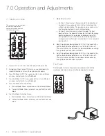
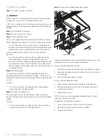
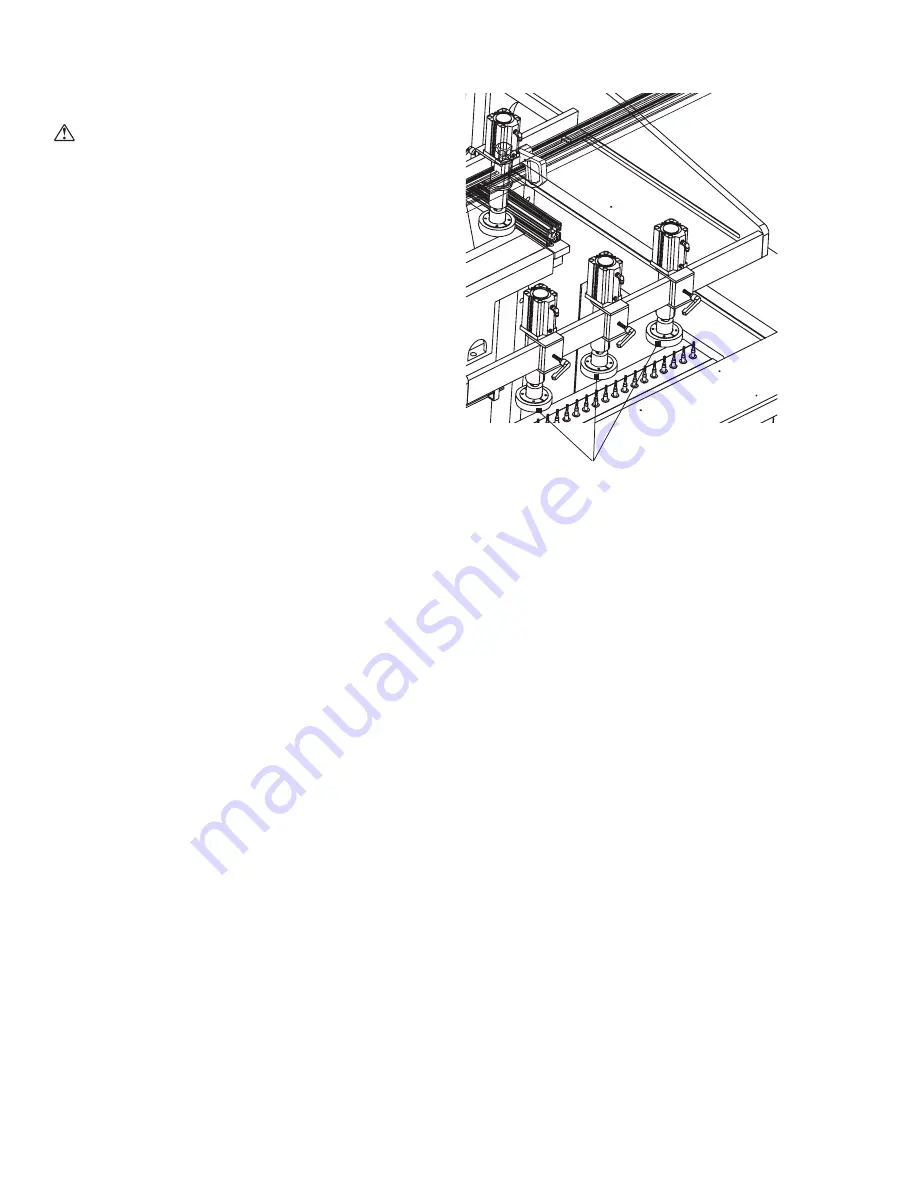
Position the workpiece hold-down clamps
Hold-down clamps
Position the hold-down clamps according to the dimensions of your
workpiece to securely hold it in place while boring.
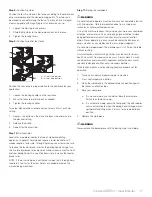
To accommodate workpiece thickness:
1. Place the workpiece on the table under the hold-down clamps.
2. Lower the hold-down clamps to within an inch of the surface of
the workpiece.
3. Lock the hold-down clamps in place.
To accommodate workpiece width:
1. Loosen the lock lever for each hold-down to be adjusted.
2. Move the hold-down(s) right or left to the optimal position to
secure your workpiece.
3. Tighten the lock levers.
NOTE: A minimum of two workpiece hold-down clamps should
always be used when possible.
To reposition the hold-down assembly:
1. Loosen the lock levers at each end of the assembly.
2. Move the assembly forward or back as needed.
3. Tighten the lock levers.
Summary of Contents for DBR50
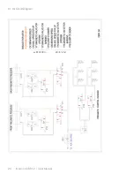
Page 20: ...Ironwood DBR50 User Manual 20 9 1 Air Circuit Diagram...
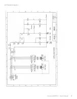
Page 21: ...Ironwood DBR50 User Manual 21 9 2 Electrical Diagram...
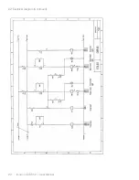
Page 22: ...Ironwood DBR50 User Manual 22 9 2 Electrical Diagram Continued...
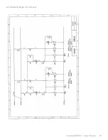
Page 23: ...Ironwood DBR50 User Manual 23 9 2 Electrical Diagram Continued...
Page 24: ...Ironwood DBR50 User Manual 24 9 2 Electrical Diagram Continued...
Page 25: ......

