DMM
‐
4880 & DMX
‐
4880 Instruction Book
Revision 0
www.irtelectronics.com
Page 8 of 16
4880
‐
DMM_4880
‐
DMX_ib_Rev0.doc
Installation
Pre
‐
installation:
Handling:
This equipment may contain or be connected to static sensitive devices and proper static free handling
precautions should be observed.
Where individual circuit cards are stored, they should be placed in antistatic bags. Proper antistatic procedures
should be followed when inserting or removing cards from these bags.
Power:
AC mains supply:
Ensure that operating voltage of unit and local supply voltage match and that correct rating
fuse is installed for local supply.
DC supply:
Ensure that the correct polarity is observed and that DC supply voltage is maintained within
the operating range specified.
Earthing:
The earth path is dependent on the type of frame selected. In every case particular care should be taken to ensure
that the frame is connected to earth for safety reasons. See frame manual for details.
Signal earth:
For safety reasons a connection is made between signal earth and chassis earth. No attempt should
be made to break this connection.
Installation in frame or chassis:
See details in separate manual for selected frame type.
Signal Connections:
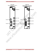
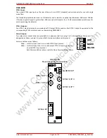
DMM
‐
4880:
STM
‐
1 Inputs:
STM
‐
1 inputs are by BNC connectors each terminated in 75
Ω
. Input cable equalisation is automatic for up to 200m
of high quality 75
Ω
coaxial cable (Belden 8281 or equivalent). No adjustments are required.
STM
‐
4 Reference Input:
The STM
‐
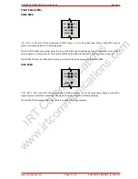
4 reference input is an option that is fitted at time of ordering. The connector type is an LC/PC (standard)
optical connector that sits next to the STM
‐
4 output, which will be the same connector type. If the STM
‐
4
reference input option is not fitted the STM
‐
4 output connector is an SC/PC (standard) type.
The standard optical detector used is a PIN detector and is rated for an optical input between
‐
3dBm and
‐
18dBm.
If the input signal strength is greater than
‐
3dBm an optical attenuator (5 or 10 dB recommended) must be used to
avoid overdriving the detector.
STM
‐
4 Output:
One STM
‐
4 NRZ encoded output is provided by an SC/PC (standard) optical connector. Should the optional STM
‐
4
reference input be fitted the connector type will be an LC/PC (standard) type to match that of the STM
‐
4 reference
input.
Alarm Outputs:
Two relay alarm output states are provided via a phoenix style 3
‐
pin plug. Pin 3 is designated as Major, pin 2 is
designated as Minor, and pin 1 is ground. Both alarms are referenced to ground.
Alarm conditions are as follows:
Major Not
used;
Minor Switch to Open Circuit on no valid input STM
‐
1 streams present.
Both Major and Minor alarms switch to Open Circuit on power failure.
1 GND
2 MINOR
3 MAJOR
IRT
Communications
www.irtcommunications.com


