4230-mmm & 4230-mmx.ib.rev4.doc
Page 9 of 17
17/10/2007
Installation
Pre-installation:
Handling:
This equipment may contain or be connected to static sensitive devices and proper static free handling precautions
should be observed.
Where individual circuit cards are stored, they should be placed in antistatic bags. Proper antistatic procedures
should be followed when inserting or removing cards from these bags.
Power:
AC mains supply: Ensure that operating voltage of unit and local supply voltage match and that correct rating
fuse is installed for local supply.
DC supply:
Ensure that the correct polarity is observed and that DC supply voltage is maintained within
the operating range specified.
Earthing:
The earth path is dependent on the type of frame selected. In every case particular care should be taken to ensure
that the frame is connected to earth for safety reasons. See frame manual for details.
Signal earth:
For safety reasons a connection is made between signal earth and chassis earth. No attempt should be
made to break this connection.
Installation in frame or chassis:
See details in separate manual for selected frame type.
Signal Connections:
All ASI & G.703 inputs and outputs are by 75
Ω
BNC connectors.
Alarm output is via a two-pin 0.1” header. Alarm condition is when there is a short between these two pins. This
corresponds to either a loss of power or if there is an input data rate violation on the MMM-4230, or a loss of power
or a loss of G.703 input on the MMX-4230.
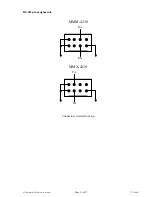
RS-422 data input and output connections are made via HE-14 8 pin double row connectors on both the MMM-
4230 and the MMX-4230.
SNMP:
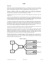
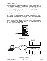
When used in an IRT FRU400 Frame with a CDM400 SNMP Module fitted, the MMM-4320 and MMX-4320 can
be interrogated by an SNMP Network Management System and certain functions can also be remotely controlled.
For instance, the channel bandwidth assignment can be altered and any the RS errors that have occurred can be
read.
SNMP Traps on alarm states can be optionally sent.
The MIB (management information base) associated with these devices has the following OIDs (Object Identies):
Alarms
Channel Present
Channel Enabled
Channel Measured Data Rate
Channel Rate Alarm Channel
Channel Packet size
Bandwidth Allocation
Framing
FPGA Version
Reset
Trap Enable
RS Errors


