3465&3485-mfc.ib.rev4.doc
page 11 of 22
17/10/2007
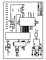
Front & rear panel connector diagrams
The following front panel and rear assembly drawings are not to scale and are intended to show relative positions of
connectors, indicators and controls only.
INPUT
SYNC
204
188
DC
MFC-3465
N140
INPUT
SYNC
204
188
DC
MFC-3485
N140
3465
ASI OUT
G.703 IN
ALARM
3485
ASI IN
G.703 OUT
ALARM
SPI_OUT


