iRBX6GF User’s Manual
UM-iRBX6GF-4.5.1-EN.docx
Pages 8 of 119
HARDWARE OVERVIEW
3.1
Front Panel
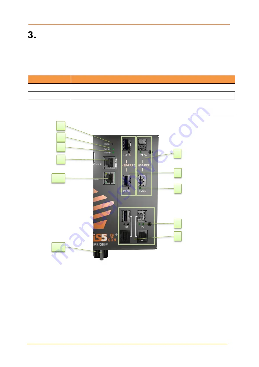
The following table describes the labels that are used on the iRBX6GF series.
Table 1 – iRBX6GF Front Panel
Port
Description
SFP ports
4 x 100 /1000Base-X SFP ports
Combo Ports
2 x 10/100/1000Base-T(X) or 2 x 100 /1000Base-X SFP ports
Management Port
1 x 100Base-T(X) port
Console
An RS-232 Serial interface; use RS-232 with RJ-45 connector to manage switch.
iRBX6GF
1.
100/1000 Base-X SFP ports (Ports 1 &2)
2.
100/1000 Base-X SFP ports (Ports 3 &4)
3.
LED for SFP ports link status
4.
LED for Combo ports link status
5.
Combo ports (Ports 5&6)
6.
Reset button. To reset, push the button
for 3 seconds
7.
LED for Alarm. When the light on, it means
failure
8.
LED for Power. When the Power is UP,
the green led will be light on
9.
Console port
10.
Management port
11.
Power connector
1
2
3
4
5
6
7
8
9
10
11


