26
C
ONNECTING
AC P
OWER
C
HAPTER
8
E
LECTRICAL
W
IRING
•
The plug connector and wire gauge sizing is to be selected with appropriate design as per the Elec
-
trical code for a 60W, 1-phase device.
Note for IT power distribution systems:
1)
This product is also designed for IT power distribution system with phase-to-phase voltage 230 V.
2)
This equipment must be connected to an earthed mains socket-outlet.
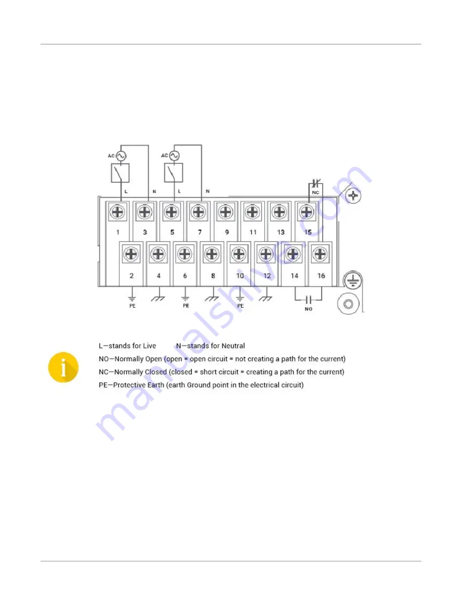
Figure 1:
AC Wiring Diagram
To establish AC power connection with the power source turned off, follow the steps below. When
following the instructions, refer to
1.
Remove the transparent plastic finger safe cover from the face of the terminal block.
If an AC power supply has been installed in PS1, perform steps 2 through 4.
2.
Connect the ground from the first power source to GND1 terminal screw (pin 2).
3.
Connect the Live from the first power source to the PWR1 V+/L terminal screw.
4.
Connect the Neutral from the first power source to the PWR1 V-/N terminal screw.
If an AC power supply has been installed in PS2, perform steps 5 through 7.
5.
Connect the ground from the second power source to GND2 terminal screw (pin 6).
6.
Connect the Live from the first power source to the PWR2 V+/L terminal screw.


