S p e z i a l e l e k t r o n i k G m b H
iseg Spezialelektronik GmbH
Email: sales@iseg-hv.de
Phone ++ 49 (0)351 / 26 996 - 0
Bautzner Landstr. 23
http://www.iseg-hv.com
Fax
++ 49 (0)351 / 26 996 - 21
D - 01454 Radeberg / Rossendorf
Germany
2
1. General information
The crates ECH 128 or ECH 12A are able to carry up to 8 or 10 HV-modules in
3U-Eurocassette with H15
connector
and one
universal interface board
. The crates provide the necessary supply voltages and the
connections for all remote control capabilities.
During operation enough air flow has to be given to the unit.
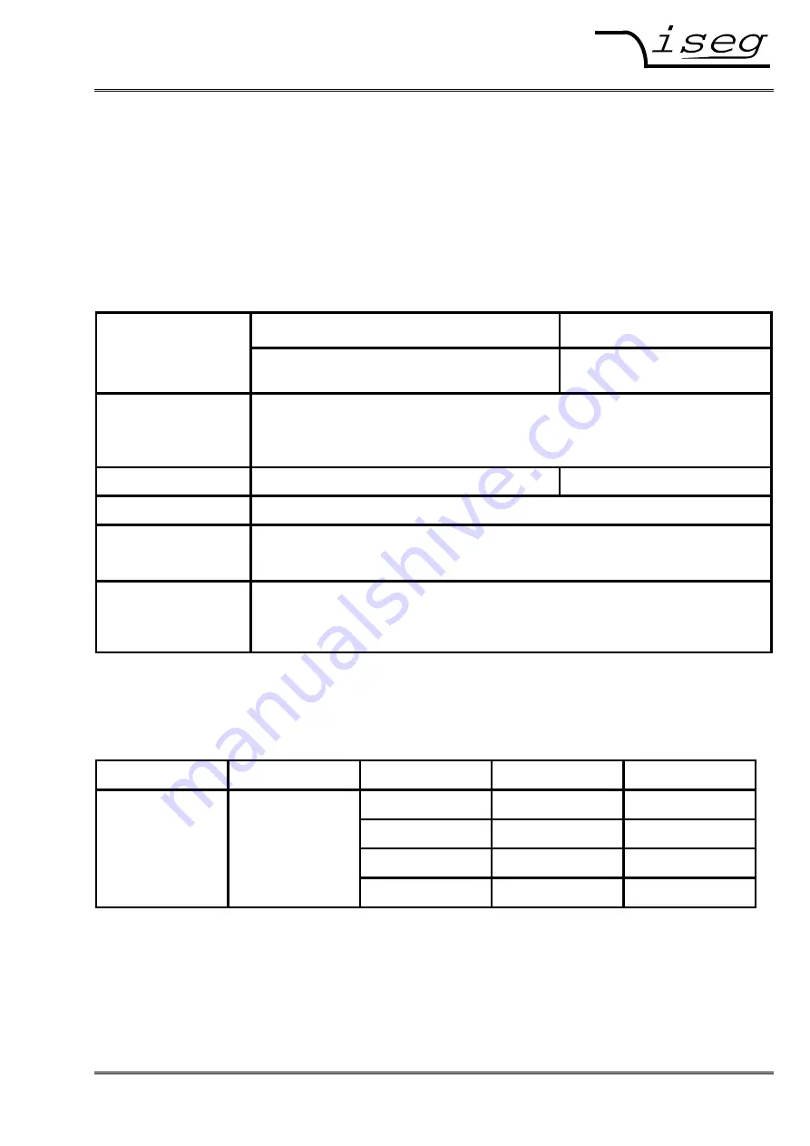
2. Technical data
ECH 128
ECH 12A
8 slots
7
∗
8TE (40,64mm) + 1
∗
max. 12TE (60,96mm)
10 slots / 8 TE (40,64mm)
AC supply voltage
Before connecting to the local mains it must be proofed that the nominal line voltage
of this unit is equal to the local mains.
Power: Vin = 100 - 240 V-AC
DC supply voltages
+ 24 V ( up to 6,25 A)
+ 24 V ( up to 6,25 A)
Power total
max. 150 W
INHIBIT
Lemo-hub on the rear, connected with INHIBIT-signal from all HV-modules
TTL level, LOW = active
⇒
V
OUT-X
= 0
Mechanical layout
19“ – 3U Standard BIN (84 TE) / ca. 320 mm depth
Module slot depth 160 mm
CAN-connectors: 9-pin Sub-D
3. PIN assignment
The external CAN-Bus is connected through 9-pin Sub-D connectors on the rear panel:
Input Output PIN Signal
Description
2
CAN_L
9-pin 9-pin 3
CAN_GND
GND
Sub-D connector
Sub-D connector
5
CAN_SHLD
Shield
female male
7 CAN_H


