S p e z i a l e l e k t r o n i k G m b H
iseg
c/o ROTECH
Email: sales@iseg-hv.de
Phone ++ 49 351 / 26 95 - 260
Spezialelektronik
Bautzner Landstr. 45
http://www.iseg-hv.com
Fax
++ 49 351 / 26 95 - 261
24
GmbH
D - 01454 Rossendorf
Germany
4.4 Implementation in the CAN-Bus
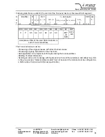
The data frame structure is matched to the message frame of the standard-format according to CAN
specification 2.0A, whereas looking from the point of view of the CAN protocol a pure data
transmission will be done, which is not applying to the protocol.
The data frame of the DCP will be transferred as data-word with n bytes length in the data field of
the CAN frames according to the specific demands of the respective access. Therefore this results
into a Data Length Code (DLC) of the CAN-protocol of n.
It is possible to transfer 8 data bytes that apply to the DLC field with falling values.
The RTR Bit is always set to zero.
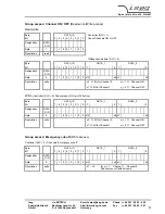
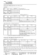
The information for the direction of the data transfer (DATA_DIR) is written in the lowest bit ID0 of
the 11 Bit CAN-Identifier.
The controller therefore will start a read-write access for data with DATA_DIR = 1 and will send with
DATA_DIR = 0.
The Front-end device responds to the data request with sending the corresponding data with
DATA_DIR = 0.
Only if the Front-end device is not registered at the controller respectively if it does not receive valid
data during a longer time period (ca. 1 min), then it will actively send the registration frame with
DATA_DIR = 1 (see also item 4.3)
Therefore it follows that all even CAN-ports (Identifier) are interpreted as ‘Write ports’ all odd CAN
ports as ‘ Read ports’.
The addressing of the Front-end device is also made with the 11 bit identifier of the CAN protocol.
In order to keep the CAN segment open also for other protocols, the addressing room was limited to
64 nodes.
ID10 is dominant.
ID9 - is always dominant for module’s witches have not an Active-CAN message function.
- is recessive for module’s witch have an Active-CAN message function when receive or
send write- or read- write-accesses and is dominant when the module active send a
error message.
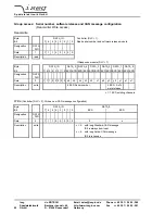
The module was configured as a CAN-node with an Active-CAN message function (see
Group
access: Serial number, software release and CAN message configuration
). In this case the
module will send this group access as an active error message with higher priority (ID9 = 0)
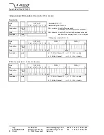
than normal messages, if one of the sumstatus- and safety loop-bits in the group access
“General status module”
not has been set.
ID3 to ID8 allows to address up to 64 Front-end devices (ID3: A0 = 2
0
;...; ID8: A5 = 2
5
),
ID2 is not used.
In one CAN segment only modules are allowed with different identifiers and the same bit rates.
The factory fixed bit rate is written on the sticker of the 96-pin connector.


