background image

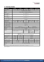
2 Technical Data

SPECIFICATIONS

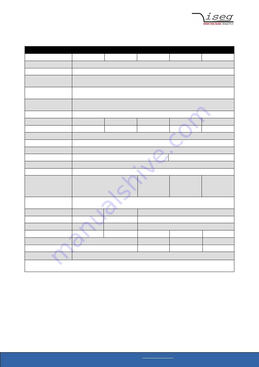
EPS 60W

EPS 3U

EPS 150W

 EPS 60W CLD

EPS 150W CLD

Output voltage V

nom

500 V – 30 kV

500 V – 30 kV

1 kV – 30 kV

500 V – 30 kV

1 kV – 30 kV

Polarity

Factory fixed, positive or negative

Stability

∆V

out

 < 0.05% • V

nom

 , after 0.5 h warmup for 8 h

Voltage regulation 

(1

 – 

[ΔV

out

 vs. ΔV

in

]

∆V

out 

< 0.01% • V

nom

Voltage Regulation 

(1

 – 

[ΔV

out

 vs. ΔR

load

]

∆V

out 

< 0.02% • V

nom

Current regulation 

(1

 –

[ΔI

out

 vs. Δv

in

], [ΔI

out

 vs. ΔR

load

]

∆I

out

 < 0.02% • I

nom

Temperatur coefficient

100 ppm/K

Supply voltage V

in

22.8 V – 26.4 V

22.8 V – 26.4 V

21 V – 29 V

22.8 V – 26.4 V

21 V – 29 V

Supply current I

in

< 3.5 A 

< 3.5 A 

< 9 A

< 3.5 A 

< 9 A

Set / Monitor voltage V

set

0 - 5 V | opt. 0 - 10 V

Set / Monitor accuracy

± 1 % • V

nom

CLD Repeat accuracy

< 0.01 •


 V

out

Voltage ramp up/down

0.25 • V

nom 

/ s

< 50 ms to V

nom

Protection

Overload and short circuit protected, INHIBIT, overvoltage / overtemp protection

Interlock

optional

Cooling

Convection cooling must be sufficient 
under load conditions

Forced cooling 
with integrated 
fan

Convection 
cooling must be 
sufficient under 
load conditions 

Forced cooling 
with integrated 
fan

2-pin screw terminal

PWR_+ 24V
PWR_0V (internally connected with 0V and GND potential)

Remote connector

D-Sub 9

H15

D-Sub 9

HV connector

HV-cable

SHV | GES

HV-cable

Case

metal box

3U cassette

metal box

Dimensions – L/W/H

185/108/57 mm

3

60.96mm/12HP/3U 170/188/60 mm

3

185/108/57 mm

3

170/188/60 mm

3

Operating temperature

-20 – 50 °C

-20 – 65 °C

-20 – 50 °C

-20 – 65 °C

Storage temperature

-20 – 85 °C

-20 – 85 °C

-20 – 85 °C

-20 – 85 °C

Humidity

20% – 90%, non-condensing

Notes:

1)

 Specifications for stability, regulation, ripple and noise are guaranteed in the range 2% • V

nom

 < V

out

 ≤ V

nom

Table 1: Technical data

EPS  High Voltage Power Supply series | Last changed on: 2020-12-02 | 

www.iseg-hv.com

10/36

Summary of Contents for EPS 150W

Page 1: ... from 500V 30 kV 60 W and 150 W versions patented resonance converter technology high efficiency available as metal box or 3U MMC only 60 W version combinable in a multichannel THQ AC DC HV power supply voltage and current control low ripple and noise low EMI multiple options INTERLOCK ARC CLD customized versions on request www iseg hv com ...

Page 2: ...tion without a written permission of iseg Spezialelektronik GmbH This information has been prepared for assisting operation and maintenance personnel to enable efficient use The information in this manual is subject to change without notice We take no responsibility for any mistake in the document We reserve the right to make changes in the product design without reservation and without notificati...

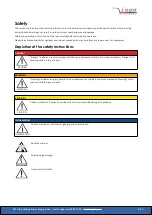
Page 3: ...ty instructions DANGER DANGER Danger indicates a severe injury hazard The non observance of safety instructions marked as Danger will lead to possible injury or death WARNING WARNING Warning indicates an injury hazard The non observance of safety instructions marked as Warning could lead to possible injury or death CAUTION CAUTION Advices marked as Caution describe actions to avoid possible damage...

Page 4: ... on the basis of his technical training his knowledge and experience as well as his knowledge of the relevant regulations General safety instructions Observe the valid regulations for accident prevention and environmental protection Observe the safety regulations of the country in which the product is used Observe the technical data and environmental conditions specified in the product documentati...

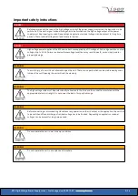
Page 5: ...RNING WARNING To avoid injury of users it is not allowed to open the unit There are no parts which can be maintained by users inside of the unit Opening the unit will void the warranty WARNING WARNING The high voltage cable must be professionally connected to the load and the connection insulated with the appropriate dielectric strength Do not power the load of its specified range WARNING WARNING ...

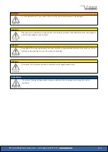
Page 6: ...ON A specified air flow rate see chapter 2 Technical Data has to be guaranteed under any circumstances The air inlet and outlet openings must not be covered or obstructed CAUTION CAUTION The devices 3UC must only be used in combination with iseg approved crates INFORMATION INFORMATION The shield of the high voltage output is always connected to the housing and can be used as a return conductor EPS...

Page 7: ...g of capacitors 19 3 4 2 Interlock EPS 150W 19 3 4 3 Ramp 19 3 4 4 INHIBIT 20 3 4 5 ARC Management 20 Devices without option ARC 20 Devices with Option ARC 21 3 4 6 VLN 21 3 4 7 CAR 21 3 5 Analogue I O interface AIO 22 3 5 1 Interface connector D SUB 9 EPS metal box 22 3 5 2 System connector H15 EPS 3UC 23 3 5 3 Reference 24 3 5 4 Set values 24 3 5 5 Monitor voltages 24 3 5 6 ON 24 3 6 Connector a...

Page 8: ...ector H15 EPS 3UC 33 7 Order guides 33 8 Appendix 34 9 Glossary 35 10 Warranty Service 36 11 Disposal 36 12 Manufacturer contact 36 EPS High Voltage Power Supply series Last changed on 2020 12 02 www iseg hv com 8 36 ...

Page 9: ...system The output voltage and current can be controlled and monitored via an analogue interface The modules are equipped with INHIBIT and INTERLOCK optional The patented resonance converter technology and metal box shielding guarantee lowest electromagnetic interference To fit best in different applications EPS modules can be equipped with ARC management or as capacitor charger with very low outpu...

Page 10: ...n Overload and short circuit protected INHIBIT overvoltage overtemp protection Interlock optional Cooling Convection cooling must be sufficient under load conditions Forced cooling with integrated fan Convection cooling must be sufficient under load conditions Forced cooling with integrated fan 2 pin screw terminal PWR_ 24V PWR_0V internally connected with 0V and GND potential Remote connector D S...

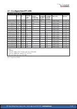
Page 11: ...5 EP040156x24z 3UC ARC A0 EPx 50 126 24 y 5 kV 12 mA 2 5 64 1 4 500 EP050126x24z 3UC ARC A0 EPx 60 106 24 y 6 kV 10 mA 0 5 64 3 6 500 EP060106x24z 3UC ARC A0 EPx 80 705 24 y 8 kV 7 mA 4 22 9 500 EP080705x24z 3UC ARC A0 EPx 100 605 24 y 10 kV 6 mA 1 22 9 500 EP100605x24z 3UC ARC A0 EPx 150 405 24 y 15 kV 4 mA 120 6 8 13 5 330 EP150405x24z 3UC ARC A0 EPx 200 305 24 y 20 kV 3 mA 400 3 55 330 EP200305...

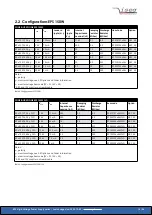
Page 12: ...26 24 y CLD 5 kV 12 mA 24 6 2 35 500 EP050126x24zCLD 3UC ARC A0 EPx 60 106 24 y CLD 6 kV 10 mA 24 5 10 5 500 EP060106x24zCLD 3UC ARC A0 EPx 80 705 24 y CLD 8 kV 7 mA 7 6 3 2 13 5 250 EP080705x24zCLD 3UC ARC A0 EPx 100 605 24 y CLD 10 kV 6 mA 7 6 2 6 13 5 250 EP100605x24zCLD 3UC ARC A0 EPx 150 405 24 y CLD 15 kV 4 mA 6 8 2 8 13 5 330 EP150405x24zCLD 3UC ARC A0 EPx 200 305 24 y CLD 20 kV 3 mA 3 1 4 ...

Page 13: ... A0 1 ARC and 10V monitor not combinable Table 4 Configurations EPS 150W CONFIGURATIONS EPS 150W CLD Vnom Inom Internal Capacitance nominal nF Damping Resistor kOhm Discharge Resistor MOhm Item code Option 1 EPx 10 157 24 y CLD 1 kV 150 mA 220 0 1 8 5 EP010157x24zCLD ARC A0 EPx 20 756 24 y CLD 2 kV 75 mA 200 0 1 8 5 EP020756x24zCLD ARC A0 EPx 40 406 24 y CLD 4 kV 40 mA 14 0 3 25 EP040406x24zCLD AR...

Page 14: ... 05 0 10V optional y 10 EPp 05 127 24 10 3U MMC capable version 3UC ARC management 1 ARC Capacitor charger CLD Capacitor charger and ARC management 1 CAR VERY LOW NOISE VLN Notes 1 for Set Monitor voltage 5V only Table 6 Technical data Options and order information EPS High Voltage Power Supply series Last changed on 2020 12 02 www iseg hv com 14 36 ...

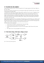
Page 15: ...stor connected to the output capacitance limits the output current during a load change or ARC High voltage power supplies of this class work with a fixed switching frequency The output parameters are controlled via a pulse width modulation PWM The control circuit controls and limits the output voltage and current corresponding to the set values Normalized monitor voltages for voltage and current ...

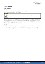
Page 16: ...this threshold is reached e g through an internal defect high voltage generation is stopped and an error register is set which blocks the high voltage generation To reset the error register the INHIBIT signal must be activated set low EPS 150W The supply voltage and internal auxiliary voltages of this high voltage supply are monitored for undervoltage and overvoltage If one of these voltages is ou...

Page 17: ...be activated set to low 3 2 3 Switch on monitoring EPS 150W When the device is switched on by applying the supply voltage an error register receives a set command for a period of 350 ms This prevents unwanted high voltage generation The error state can only be reset after this time by an activated INHIBIT signal If operation without the INHIBIT function is desired e g to control the device exclusi...

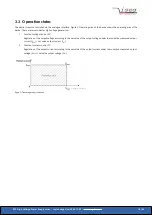
Page 18: ...utput voltage according to the set value of the output voltage under the condition measured output current IMON set value output current ISET 2 Constant current control CC Regulation of the output current according to the set value of the output current under the condition measured output voltage VMON set value output voltage VSET Figure 2 Operating area of the device EPS High Voltage Power Supply...

Page 19: ...must be less than 300 Ohm If the safety loop is open Impedance 100 kOhm the relays will open The high voltage generation is stopped only by the opened relay contacts The relay locks the gate pulses of the semiconductors of the inverter It is not possible to switch on the high voltage generation if the safety loop is open The state of the opened safety loop is handled as an error For the release of...

Page 20: ...or memory Table 7 Inhibit 3 4 5 ARC Management For HV sources in metal box with the optionally ARC management an ARC signal is present at pin ARC of the connector AIO In the case of an ARC this signal has a low level for approximately 1 millisecond By applying a low level signal at pin INH of the connector AIO INHIBIT the ARC signal also has a low level For HV sources in 3UC housing with the ARC m...

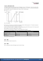
Page 21: ...ed with the voltage ramp ARC Ramp For HV sources in metal box with ARC management an ARC signal is present at pin ARC of the connector AIO In the case of an ARC this signal has a low level for a approximately 1 millisecond HV sources in 3UC housing with ARC management are not equipped with an ARC signal The parameters of the ARC Management are shown in Table 9 Parameters of the ARC Management EPS ...

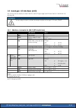
Page 22: ...wn the output voltage TTL level LOW HV OFF HIGH or n c HV ON 4 ISET Set voltage of output current 0 5 V opt 0 10 V 1 Ri 10 MOhm 5 ON HV ON OFF with voltage ramp TTL level LOW HV ON HIGH or n c HV OFF 6 Without option ARC GND Signal ground With option ARC ARC Signal ARC TTL level LOW ARC approx 1 ms INH active low HIGH no ARC 7 VMON Monitor voltage 0 5 V opt 0 10 V 1 8 VSET Set value of output volt...

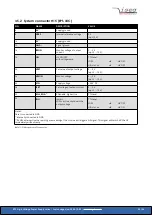
Page 23: ...0 5 V opt 0 10 V 26 VIN Supply voltage 24 V DC 28 ISET Set voltage of output current 0 5 V opt 0 10 V 30 KILL_ENA 2 Killenable high active TTL level 32 INH Inhibit LOW active shut down the output voltage TTL level LOW HV OFF HIGH or n c HV ON Notes Case is connected to GND 1 internally connected to GND 2 If KillEnable is active the reaching or exceeding of the Iset value will trigger a Kill signal...

Page 24: ...not connected the set value is internally set to Vref 3 5 5 Monitor voltages Monitor voltages 0 5 V1 proportional to the output voltage and output current are available at pin VMON and pin IMON of the connector AIO respectively reference potential GND 3 5 6 ON By applying a low level signal at pin ON of the connector AIO the high voltage ramps down with the specified voltage ramp speed After a ris...

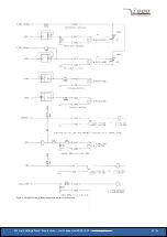
Page 25: ...Figure 4 Electrical wiring of the analogue and digital in and outputs EPS High Voltage Power Supply series Last changed on 2020 12 02 www iseg hv com 25 36 ...

Page 26: ...the high voltage output of the power supply must be properly grounded Depending on application residual voltages can be present for long time periods These residual voltages can lead to severe injuries CAUTION CAUTION The HV cable has to be connected to the load properly and isolated according to proof voltage CAUTION CAUTION The shield of the high voltage output is always connected to the housing...

Page 27: ...age Check environmental temperature and cooling conditions Check control Check INHIBIT function External fuses trip during switch on Use fuses with slow characteristic inrush current 25 A 3 8 Maintenance Repair and maintenance may only be performed by trained and authorized personnel INFORMATION INFORMATION For compliance of the specified accuracy of set and monitor signals the unit has to be reca...

Page 28: ...nal drawings Figure 5 Dimensional drawing EPS 60W Cable Figure 6 Dimensional drawing EPS 3U Cassette with SHV HV connector 8kV EPS High Voltage Power Supply series Last changed on 2020 12 02 www iseg hv com 28 36 ...

Page 29: ...Figure 7 Dimensional drawing EPS 3U Cassette with GES HV connector 10 kV EPS High Voltage Power Supply series Last changed on 2020 12 02 www iseg hv com 29 36 ...

Page 30: ...Figure 8 Dimensional drawing EPS 150W EPS High Voltage Power Supply series Last changed on 2020 12 02 www iseg hv com 30 36 ...

Page 31: ...5 Ground bolt connection Figure 9 Detail drawing of Figure 8 Figure 10 Ground bolt connection EPS High Voltage Power Supply series Last changed on 2020 12 02 www iseg hv com 31 36 ...

Page 32: ...Connector 57K101 006N3 Z590162 S08 RADIALL 8 kV Socket R317 580 000 Connector R317 005 000 Z592474 G11 GES 10 kV Socket 7311020 Connector 7310020 Z592516 G21 GES 20 kV Socket 7321020 Connector 7320020 Z592391 G31 GES 30 kV Socket 7331053 Connector 7331052 Z592501 6 2 Interface connector D SUB 9 EPS metal box D SUB9 CONNECTORS Name D SUB9 Figure EPS High Voltage Power Supply series Last changed on ...

Page 33: ...er Information CLD Capacitor Charger 00 Cable 02 SHV 03 S08 06 G11 07 G21 08 G31 00 none Table 12 Configuration item code CABLE ORDER GUIDE POWER SUPPLY SIDE CONNECTOR CABLE CODE CABLE DESCRIPTION LOAD SIDE CONNECTOR ORDER CODE LLL length in m 1 SHV 04 HV cable shielded 30kV HTV 30S 22 2 open SHV_C04 LLL S08 04 HV cable shielded 30kV HTV 30S 22 2 open S08_C04 LLL G11 02 Lemo HV cable shielded 30kV...

Page 34: ...https iseg hv com download DC_DC EPS iseg_manual_EPS_en pdf Iseg crates 3UC https iseg hv com de products detail MME Crates Iseg THQ https iseg hv com de products detail THQ Application note Coming soon EPS High Voltage Power Supply series Last changed on 2020 12 02 www iseg hv com 34 36 ...

Page 35: ...erance tube Vset Vbounds around Vset Inom nominal output current Iout output current Iset set value of output current Imon monitor voltage of output current Imeas digital measured value of current Itrip current limit to shut down the output voltage Iin input supply current Imax limit max value of output current Ilimit Current Limit Ibounds Current bounds a tolerance tube Iset Ibounds around Iset P...

Page 36: ...rt rma 11 Disposal INFORMATION INFORMATION All high voltage equipment and integrated components are largely made of recyclable materials Do not dispose the device with regular residual waste Please use the recycling and disposal facilities for electrical and electronic equipment available in your country 12 Manufacturer contact iseg Spezialelektronik GmbH Bautzner Landstr 23 01454 Radeberg OT Ross...

Reviews: