3.5.3 Reference
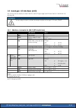
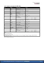
A reference voltage of 5.05 V (optionally 10.1 V) is available at pin “V
REF
” of the connector “AIO”. The reference can be used to
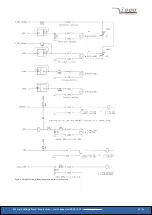
preset the set values via potentiometers, as shown in Figure 4: Electrical wiring of the analogue and digital in- and outputs. With
a total load of 10 k
Ω
between the reference output and GND the reference voltage at the connector is 5.0 V (10.0 V).
3.5.4 Set values
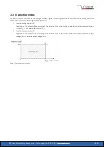
A voltage between 0 – 5 V
at pin “V
SET
” (reference potential GND) of the connector “AIO” controls the output voltage between
0 – V
nom
. Similarly, at pin “I
SET
” the output current is controlled between 0 – I
nom
. If the Pin “I
SET
” not connected, the set value is
internally set to V
ref
.
3.5.5 Monitor voltages
Monitor voltages (0 – 5 V
1
) proportional to the output voltage and output current are available at pin “V
MON
” and pin “I
MON
” of the
connector “AIO”, respectively (reference potential GND).
3.5.6 ON
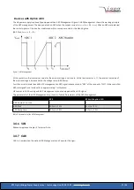
By applying a low level signal at pin “ON” of the connector “AIO“, the high voltage ramps down with the specified voltage ramp
speed. After a rising edge of a signal at pin “ON” of the connector “AIO“ the output voltage increases with the ramp speed or the
given output current to its set value (pin “V
SET
” of the connector “AIO”) or until the set value of the output current is reached
(pin “I
SET
” of the connector “AIO”, see chapter 3.5 Analogue I/O interface (AIO)).
1
optionally 0 – 10 V
EPS High Voltage Power Supply series | Last changed on: 2020-12-02 |
www.iseg-hv.com
24/36

