S p e z i a l e l e k t r o n i k G m b H
iseg Spezialelektronik GmbH
Email: sales@iseg-hv.de
Tel ++ 49 (0)351 / 26 996 - 0
Bautzner Landstr. 23
http://www.iseg-hv.de
Fax ++ 49 (0)351 / 26 996 - 21
16
D - 01454 Radeberg/ Rossendorf
5
Operation
5.1
Operating mode
LOCAL
The device can be controlled with the buttons and the rotary encoders of the front panel. The led “REMOTE” is not illuminated.
REMOTE
For remote control, the corresponding interface (USB, CAN, RS-232, USB, IEEE-488, Ethernet, AIO) must be specified first
via the menu item “F07 Set Interfce”. The device switches to REMOTE mode when receiving the first command from a digital
interface. The led “REMOTE” is not illuminated.
5.2
Front panel operation
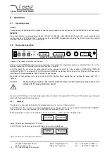
Figure 5.1: Front panel (HV connector at the front)
After pushing the POWER button the device is booting. During boot, the integrated hardware is initialized. After start-up the
device is working in LOCAL mode and the KILL function is “disable”.
In LOCAL mode, the set values for voltage and current can be adjusted with the rotary encoders VOLTAGE for VSET and
CURRENT for ISET. The yellow LEDs VOLTAGE and CURRENT are lighting. When trying to set VSET or ISET beyond the
adjusted limit, the corresponding LED is flashing for one second.
Generation of high voltages starts by pushing the ON/OFF button. While generating high voltage, the green LED “HV” is
lighting.
Caution!
The high voltage which has been selected with the rotary encoders is going to ramp to the chosen
voltage with the programmed ramp speed!
By pressing ON/OFF again, the high voltage generation is turned off, the green LED “HV” turns off. The high voltage is ramped
down with the programmed ramp speed.
5.2.1
Displays
The device has two eight digit displays for voltage and current as well as for Menu control.
In HV-OFF state, the set values are shown on display for easy changes with the rotary encoders VOLTAGE and CURRENT.
These set values are stored in processor’s EEPROM and reloaded at next start-up.
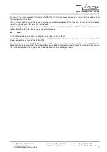
While displaying the set values for voltage and current, a small ’s’ is flashing at the left display side:
Figure 5.2: Set values the display in HV OFF state
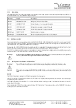
In HV-ON state the measured values of voltage and current are displayed:
Figure 5.3: Set values the display in HV ON state
HIGH VOLTAGE POWER SUPPLY
VOLTAGE
CURRENT
ON
OFF
KILL
ESC
LOCAL
MENU
POWER
HV
KILL
ENABLE
REMOTE
ERROR
RxD
TxD
CV
CC
iseg
HPp 10 807
1kV / 800mA
VOLTAGE
CURRENT
HV OUT
0 V
1.000kV
800.0mA
1
O
s1.000kV
s800.0mA
0.995kV
752.3mA

