S p e z i a l e l e k t r o n i k G m b H
iseg Spezialelektronik GmbH
Email: sales@iseg-hv.de
Tel ++ 49 (0) 351 / 26 996 - 0
Bautzner Landstr. 23
http://www.iseg-hv.de
Fax ++ 49 (0) 351 / 26 996 - 21
D - 01454 Radeberg/ Rossendorf
19
5.2.4
Error states
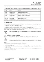
The following Events cause the High Voltage to shut down without ramp and have to be cleared with Button KILL/ESC or a
remote command (e. g. *CLS) before turning it on again.
Event Bit
Display
Description
EEMCY
EMERGENCY OFF
Emergency off via remote control
ETRIP
CURRENT TRIP
Current trip (I
OUT
≥
I
SET
) in mode Kill enable
EVLIM
VOLTAGE LIMIT
Voltage limit exceeded in mode Kill enable
ECLIM
CURRENT LIMIT
Current limit exceeded in mode Kill enable
ESFLPngd
SAFETYLOOP
Safety loop was or is open
ETEMPngd
OVERTEMPATURE
Maximum allowed temperature was or is exceeded
5.3
Interface control
For remote control, the corresponding interface (USB, CAN, RS-232, USB, IEEE-488, Ethernet, AIO) must be specified first
via the menu item “F07 Set Interfce”. The device switches to “REMOTE” mode when receiving the first command from the
selected interface. The yellow LED “REMOTE” is illuminated.
By pressing the “LOCAL/MENU” button the remote control is suspended. The device can now be controlled from the front
panel. When receiving new commands via Interface, the device switches back to “REMOTE” mode.
If “HV-ON” is activated while the device is controlled via a remote interface, high voltage can be turned off by pressing the
“ON/OFF” button. In this case the device switches to “LOCAL” mode.
Warning!
If local control is disabled (Local Lockout, see section
Fehler! Verweisquelle konnte nicht gefunden
werden.
), the device can only be turned off via mains switch!
5.3.1
Description of the RS-232- / USB interface
Warning!
Turn off the device with mains switch before connecting/disconnecting the interface cable.
Caution!
If the device is equipped with RS-232 and USB Interface, only one of them must be connected to the
HPS.
RS-232
The RS-232 interface is located at a D Sub 9 connector on the back panel.
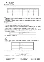
The electric transfer is performed via RxD and TxD, which are related to floating GND of the Interface. The D-Sub 9 pin
assignment is given in Table 5.1.
The cable connection to the computer is 1:1 (no zero modem-cable!). If no 9-pin cable is available, connections must be set
up as shown in the table.
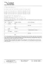
For remote control, “RS-232” must be selected in Menu “F07 Set Interfce“. The device switches to the “REMOTE” state when
receiving the first command via interface.

