8 Description of control, status, event, and mask registers
8.1. Status and control register decoding
Status and control register requests are answered as an unsigned integer number. In this number, distinct bits are set or cleared.
For example, the request
(@2) could return 152, which is the sum of 128 (Bit07), 16 (Bit04), and 8 (Bit03).
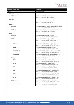
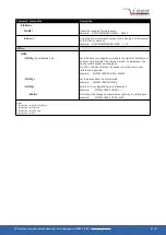
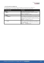
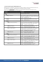
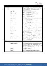
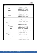
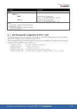
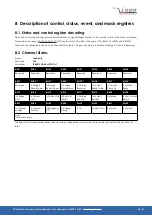
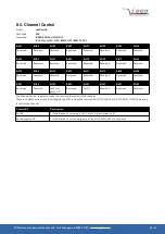
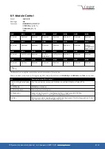
These bits can now be decoded from the Channel Status table. This gives the status: Is Constant Voltage, Is On and Is Ramping.
8.2. Channel Status
Access:
read-only
Data-Type:
UI4
Command:
:READ:CHAN
nel
:STAT
us
?
Bit31
Bit30
Bit29
Bit28
Bit27
Bit26
Bit25
Bit24
Reserved
Reserved
Reserved
Reserved
Reserved
Reserved
Reserved
Reserved
Bit23
Bit22
(1
Bit21
(1
Bit20
(1
Bit19
(1
Bit18
(1
Bit17
(1
Bit16
(1
Reserved
Is Voltage
Bound Lower
Is Voltage
Bound Upper
Is Voltage
Ramp Down
Is Voltage
Ramp Up
Is Current
Ramp Down
Is Current
Ramp Up
Is Current
Ramp
Bit15
Bit14
Bit13
Bit12
Bit11
Bit10
Bit09
Bit08
Is Voltage
Limit
Is Current
Limit
Is Current Trip Is External
Inhibit
Is Voltage
Bounds
Is Current
Bounds
Reserved
Is Low Current
Range
Bit07
Bit06
Bit05
Bit04
Bit03
Bit02
Bit01
Bit00
Is Constant
Voltage
Is Constant
Current
Is Emergency
Off
Is Voltage
Ramp
Is On
Is Input Error
Reserved
Is Positive
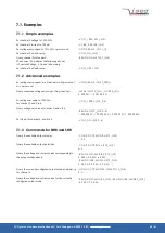
Notes:
1)
NHR and SHR only
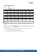
The Channel Status register describes the actual status. Depending on the current status of the channel the bits will be set or
reset.
SCPI protocol common instruction set | Last changed on: 2020-10-07 |
www.iseg-hv.com
44/61

