11
CHAPTER 2. DISASSEMBLY OF MAJOR COMPONENTS
• Use a lithium-based grease.
• There should be no oil or water leaks through
the installed soil seals.
c. O-rings
• O-rings should be coated with grease before in-
stalling.
• Installed O-rings should have no slack or twist.
• Installed O-rings should maintain proper air
tightness.
d. Snap-rings
• Snap-ring installers should be designed so as not
to permanently deform the snap-rings.
• Installed snap-rings should be seated securely
in the groove.
• Be careful not to overload the snap-ring to the
extent that it is permanently deformed.
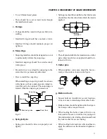
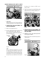
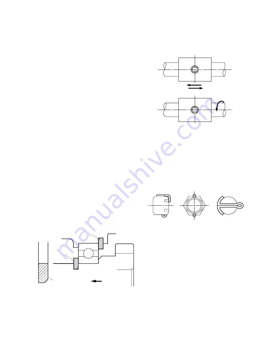
• How to install the snap-ring:
When installing a snap-ring, install it as shown
in the figure with its round edge side turned to-
ward the part to be retained. This round edge is
formed when the snap-ring is pressed out.
Fig. 2-1
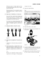
e. Spring (roll) pins
• Spring pins should be driven in properly and
tightly.
• Spring pins should be installed so that their seams
should face the direction from which the load is
applied.
Fig. 2-2
• The roll pins installed in the transmission or other
parts where much force is applied should be re-
tained with wire.
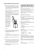
f. Cotter pins
• When installed, cotter pins should be bent se-
curely at the ends as shown in the figure.
Fig. 2-3
g. Bolts and nuts
• Special bolts are installed at several locations,
so be sure not to interchange them other bolts.
• Bolts and nuts should be tightened to their speci-
fied torque with a torque wrench.
• When locking the bolts or nuts with wire or a
lock washer, be sure to wind the wire paying suf-
ficient attention to its winding direction and bend
the lock washer for secure locking.
• When locking bolts and nuts with an adhesive,
apply the adhesive on the thread and tighten se-
curely.
Snap-ring
Snap-ring
Round edge side
Thrust force
F
F
F
Summary of Contents for SCM49
Page 1: ...S E R V I C E M A N U A L I S E K I L A W N M O W E R S LAWN MOWERS MOWER DECKS SCM48 SCM54 ...
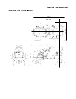
Page 7: ...7 CHAPTER 1 INTRODUCTION 3 EXTERIOR VIEW AND DIMENSIONS 1935 mm 1965 mm 1100 mm 1265 mm ...
Page 36: ...36 SERVICE MANUAL FOR SGR19 SGR17 Fig 3 55 III 3 CYLINDER BLOCK 1 EXPLODED VIEWS ...


