background image

2

SERVICE MANUAL FOR SGR19 & SGR17

FOREWARD

This service manual has been prepared to provide the information and suggestions necessary for

servicing the ISEKI SGR equipped with the hydrostatic transmission. These include construction, specifica-
tions, removal and reinstallation of the components, disassembly and reassembly instructions, inspection
and adjustment instructions, troubleshooting, general precautions etc.

Figures mentioned in this manual are standard values established by ISEKI for the SGR, conse-

quently when a non-ISEKI part has been installed on the machine or adjustments and repairs have been
made in a manner other than as specified in this manual, the pertinent values mentioned herein are no longer
valid. ISEKI does not assume responsibility for problems or damage caused by a value deviation due to
maladjustment or by the use of unauthorized parts.

Servicing procedures outlined in the manual contain sufficient informa-

tion to return all component parts of a machine to new condition. In discussion of each
component part, it is assumed that a complete overhaul is being performed, conse-
quently, complete disassembly and reassembly are outlined. The machine is relied
upon to decide how far disassembly must be carried out when complete overhaul is not
required.

Study unfamiliar service procedures thoroughly and understand them clearly

before attempting disassembly. Specific data essential for proper overhaul, such as
running clearances and torque values, have been provided in interline of inspection
and reassembling procedures of each group section.

This manual was compiled from latest information available at time of

publication, However ISEKI reserves the right to make changes at any time without
notice.

Whenever the terms “left” and “right” are used, this means as viewed by

the operator when seated in the operator’s seat.

Whenever servicing the machines, pay sufficient attention to the opera-

tional safety to protect you and other persons around the machines from danger by
following carefully the instructions given in the manual. Never take chances!

Summary of Contents for SCM49

Page 1: ...S E R V I C E M A N U A L I S E K I L A W N M O W E R S LAWN MOWERS MOWER DECKS SCM48 SCM54 ...

Page 2: ...ma tion to return all component parts of a machine to new condition In discussion of each component part it is assumed that a complete overhaul is being performed conse quently complete disassembly and reassembly are outlined The machine is relied upon to decide how far disassembly must be carried out when complete overhaul is not required Study unfamiliar service procedures thoroughly and underst...

Page 3: ...AND ADJUSTMENT OF NOZZLE OPENING PRESSURE AND INJECTION TIMING 22 4 1 Adjustment of the valve opening pressure of the injection nozzles 22 4 2 Inspection of oil tightness of valve seats 23 4 3 Spraying condition of injection nozzle 23 4 4 Inspection and adjustment of injection timing 23 5 COMPRESSION AND UNLOADED IDLING SPEEDS 25 5 1 Inspection of compression 25 5 2 Inspection and adjustment of th...

Page 4: ... 89 2 1 When the steering wheel is in the neutral position 89 2 2 When the steering wheel is operated 89 3 SECTION OF MINI ORBIT ROLL AND MAJOR COMPONENTS 90 4 DISASSEMBLY REASSEMBLY 91 4 1 DISASSEMBLY 91 4 2 REASSEMBLY 92 5 MAJOR TROUBLES AND CAUSES AND COUNTERMEASURES 94 CHAPTER 8 MANUAL STEERING SYSTEM 97 1 CONSTRUCTION 97 2 GEAR BOX 97 3 DISASSEMBLY 98 3 1 REMOVAL OF THE STEERING GEAR BOX ASSE...

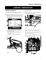
Page 5: ... H I N I P P O R I 5 C H O M E ARAKAWA KU TOKYO 116 JAPAN 1 2 3 4 1 Model a name SGR19H in the exammple 2 Type E42 or UE42 3 Production serial number 000001 in the example 4 Production year by the last two digits Fgi 1 1 Fig 1 2 b Chassis number The chassis number is punched on the left hand side of the chassis as shown below Fig 1 3 c Engine model name and serial number The engine name is cast in...

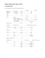
Page 6: ...m 14 19 12 2 16 5 Piston displacement cc 928 828 Combustion chamber Swirl chamber Fuel tank capcity litres 18 5 Transmission Main transmission HST Hydro Static Transmission Travelling speed Forward km h 0 16 8 Reverse km h 0 10 0 Wheelbase mm 1365 Wheel tread Front mm 860 Rear mm 860 Tyre size Front 210 60D 8 Rear 250 60D 14 Minimum ground clearance mm Steering system Power steering Manual or Powe...

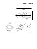
Page 7: ...7 CHAPTER 1 INTRODUCTION 3 EXTERIOR VIEW AND DIMENSIONS 1935 mm 1965 mm 1100 mm 1265 mm ...

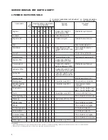
Page 8: ...raulic oil filter Replace after initial 50 h and then replace after every 200 h Suction filter Clean after initial 50 h and then clean after every 200 h Brake pedal play R 20 to 30 mm 0 8 to 1 2 in Steering wheel R Check after every 300 h There should be no abnormality Ball joints of steering R Check after every 300 h Loose ball joints should be system linkage re tightened Tyre pressure R Front 1 ...

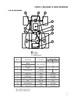
Page 9: ...2 Engine Engine oil 2 5 3 Transmission case HST oil 6 7 6 3 SHELLDONAX TD 4 Center pivot Grease As required 5 Knuckle arms Grease As required 6 Brake shaft HST hub Grease As required 7 Fuel Diesel fuel 18 5 8 Cylinder ball end Grease As required 9 Drive shaft Grease As required Use oil of better than class CC Use ISEKI s recommended oil Ref No Filling points Lubricants Fresh clean water ...

Page 10: ...ion parts Also the use of unauthorized parts will result in rela tively poor machine performance 2 PRECAUTIONS TO BE FOLLOWED WHEN INSTALLING COMMON PARTS a Roller or ball bearings When a bearing is fitted in by the outer race use an installer which is specially designed to push only the outer race and vice versa The installer must be designed to install the bear ing on the shaft in a parallel pos...

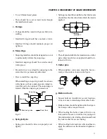
Page 11: ...ressed out Fig 2 1 e Spring roll pins Spring pins should be driven in properly and tightly Spring pins should be installed so that their seams should face the direction from which the load is applied Fig 2 2 The roll pins installed in the transmission or other parts where much force is applied should be re tained with wire f Cotter pins When installed cotter pins should be bent se curely at the en...

Page 12: ... TB1702 Each contact surface should be coated with an adhesive THREE BOND TB1215 and tight ened evenly with bolts Adhesive coated surfaces should be installed within 30 minutes after ap plication of the adhesive The contact surfaces should be flawless and free from foreign matter and especially from grease before application of the adhesive Contact surfaces of the sleeve metal support and front tr...

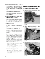
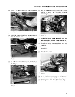
Page 13: ...wer deck rearward to detach it from the linkage Fig 2 9 7 Start the engine and lift up the linkage Then remove the mower deck sideways from the mower engine Fig 2 10 2 REMOVAL AND REINSTALLATION OF MAJOR FUNCTIONAL COMPONENTS 2 1 REMOVAL AND REINSTALLATION OF ENGINE REMOVAL 1 Open the rear fender Fig 2 11 2 Disconnect the negative post of the battery 3 Drain engine coolant through the drain plug ...

Page 14: ... for the throttle wire sheath and then remove the sheath 8 Remove the air intake pipe by loosening the air cleaner side and engine side clamps Fig 2 15 9 Remove the upper and lower hoses which con nect the radiator and engine Remove the drain hose from the cylinder block 10 Disconnect the wire harness from the engine by removing bolts and nuts which holds it Glow plug terminals Thermometer Oil pre...

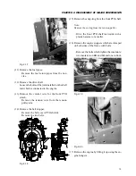
Page 15: ...nsion pulley arm 14 Remove the belt stopper Remove the belt cover PTO shield Remove the two belts 15 Remove the snap ring from the front PTO shaft Note Remove the spring from the tension pulley Drive the front PTO shaft rearwards with a plastic hammer or a mallet 16 Remove the engine stoppers which are clamped on both sides of the frame with bolts Remove the bolts which tighten the insulators two ...

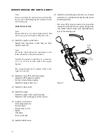
Page 16: ... not be slanted either to the right or to the left 2 Install the front PTO and related parts Install the PTO pulley and shaft Set the belt and tension pulley Install the stopper and cover 3 Install the drive shaft 4 Install fuel pipes Install the pipes on the injection pump Install the fuel return pipes on the nozzles 5 Connect wire harness Glow plug terminals Thermometer Oil pressure switch Start...

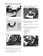
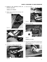
Page 17: ...e five hairpins from the dumper and the rear linkages Fig 2 22 Fig 2 23 2 Remove the wire harness from the fender Fig 2 24 3 Remove the fender Fig 2 25 4 Remove the fuel tank Fig 2 26 REMOVAL OF STEP 1 Remove the connecting bolt from the brake pedal and HST pedals Also remove the dif lock pedal at the left hand side Fig 2 27 ...

Page 18: ...SION CASE REMOVAL 1 Remove the drain plug located on the bottom of the transmission case 2 Remove the fender and step referring to 3 2 3 Remove the battery and fuel tank referring to 3 2 Fig 2 29 4 Remove the drive shaft Fig 2 30 5 Remove the following oil hoses Lifting cylinder connecting hose Solenoid valve connecting hose Fig 2 31 6 Remove the brake rod linkage and parking brake cable Fig 2 32 ...

Page 19: ... Remove the HST unit Remove the suction pipe and filter Remove the HST unit tightening bolts Then the unit can be removed from the transmission case REINSTALLATION Reinstall in reverse order of removal taking the following precautions Reinstall in reverse order of removal taking the following precautions Be sure to install O rings for all hydraulic pipes Each bolt and nut should be tightened to re...

Page 20: ... sp h 2900rpm 215 Unloaded maximum speed rpm 3150 Unloaded minimum speed rpm 1250 Fuel Diesel fuel Dry weight kg 85 Dimensions L W H mm 520 400 554 Fuel injection order 1 3 2 Direction of rotation Clockwise viewed from fan Fuel injection system Fuel injection pump model DN PD KCA P Plunger dia stroke mm 5 0 6 0 Injection nozzle Throttle type Governor Centrifugal all speed governor Valve timing Int...

Page 21: ...0 10 0 25 20 Above 25 30 Replacing intervals After the initial 50 hours of operation and then after every 100 hours Replace the oil filter cartridge after every 300 hours a REPLACEMENT OF OIL FILTER Remove the oil filter cartridge from the cylinder block using a cartridge wrench b INSTALLATION OF OIL FILTER Inject a small amount of engine oil into the car tridge Apply engine oil to the O ring of t...

Page 22: ...tween TDC in compression stroke andTDC in exhaust stroke use height difference among the push rods as a criterion for judgement When the heights of the push rods No 1 2 3 and 6 viewed from the fan are about 5 mm lower than those of No 4 and 5 the piston in No 1 cylinder is at TDC in com pression stroke 3 3 Insert a feeler gauge of a specified thickness and adjust the clearance with the adjusting s...

Page 23: ...ction pipes Note To keep away dust cap the openings of the in jection nozzle injection pump and injection pipe Fig 3 10 4 4 Inspection and adjustment of injection tim ing Confirmation of injection timing using No 1 cylinder 1 Bring the piston in No 1 cylinder to TDC in com pression by aligning the marking on the crank shaft pulley with the one on the timing gear case turning the crankshaft by hand...

Page 24: ...ng and stopper Then re tighten the delivery holder to the specified torque 11 Install the injection pipe and tighten the nut to the specified torque Tightening torque 1 5 2 5 kgf m Fuel Delivery valve Note Supply fuel only when fuel injection timing is measured only for operation 6 It is impossible to measure the fuel injection tim ing by turning the crankshaft in reverse counterclockwise viewed f...

Page 25: ...ipes in advance to avoid fuel injection Remove only the nozzle for the cylinder whose compression is to be measured Other nozzles should be left installed Caution When cranking the engine take care not to touch rotating parts 5 2 Inspection and adjustment of the idling speeds 1 Check for idling speeds Specified value 1250 rpm 2 When the measured value deviates from the specified value correct with...

Page 26: ...viating temperatures at which the valve starts to open and opens fully Put the thermostat in water and heat the water gradually by stirring Check for the temperature at which the valve starts to open and that at which the valve opens fully Fig 3 17 Starts to open 76 5 2 C temperature Full open 90 C 194 F temperature lift more than 8 mm III ENGINE BODY III 1 CYLINDER HEAD Fig 3 18 Exploded view of ...

Page 27: ...om dust 9 Removal of glow plugs 10 Removal of the cylinder head Loosen the cylinder head bolts in the sequence shown in the figure After the removal of the cylinder head remove the dowels and tappets Fig 3 23 1 REMOVAL OF THE CYLINDER HEAD 1 Removal of the cylinder head cover Fig 3 19 2 Disconnection of the injection piping When the piping has been removed cap the de livery pipe holders injection ...

Page 28: ...ottom surface and inlet and exhaust ports using COLOR CHECK Fig 3 25 2 Inspection of the cylinder head for distortion Measure the flatness of the bottom surface of the cylinder head by putting a straight rule di agonally across the four corners on the bottom face and check for clearance with thickness gauges Standard value Usable limit Distortion 0 075 mm 0 15 mm When the distortion exceeds the us...

Page 29: ... valve seat sur face and lap with the valve while tapping the valve to secure sufficiently contact with the whole circumference valve and valve guide as an assembly Measure the play at a point 10 mm apart above the valve oil seal when the valve lift is 0 mm Fig 3 27 4 Replacement of the valve guide Drive out the valve guide upwards from the cyl inder head bottom Press in a new valve guide from the...

Page 30: ... valve thickness is less than the usable limit replace the valve Fig 3 33 7 Inspection of valve springs Measure the free length of each valve spring with calipers Standard value Usable limit Free length 36 0 mm 35 0 mm Tension 8 3 kgf 7 35 kgf when compressed to 31 mm Put a spring upright on a surface table and meas ure deviation from vertical Usable limit Deviation from vertical 1 0 mm Free lengt...

Page 31: ...arm shaft When the difference exceeds the usable limit replace the assembly of the rocker arm shaft and rocker arms Fig 3 35 Usable limit Surface flatness both for intake 0 2 mm and exhaust manifolds When the deviation exceeds the usable limit replace the manifold 4 DISASSEMBLY AND INSPECTION OF THE ROCKER ARM SHAFT 1 Disassembly of the rocker arm shaft assembly Put an identification mark on the f...

Page 32: ...rod for wear Replace excessively worn rods with new ones Check push rods for bending Place a rod on a surface table and measure bend ing with thickness gauges Usable limit Push rod bending 0 3 mm Fig 3 41 6 INSTALLATION OFTHE CYLINDER HEAD 1 Installation of the cylinder head Clean the bottom surface of the cylinder head and the top surface of the cylinder block Drive in dowels Insert tappets Put a...

Page 33: ...ply engine oil to the threads of the cylinder head bolts Tighten the cylinder head bolts in the sequence as shown in Fig IV 31 to the specified torque Be sure to tighten the bolts step by step first to 2 kgf m 14 ft lbs second to 4 kgf m 29 ft lbs and then lastly to the following torques Specified torque 5 5 6 0 kgf m 1 2 3 4 5 6 7 8 9 10 11 12 13 14 Fig 3 43 2 Installation of the glow plugs 3 Ins...

Page 34: ...d cover seal and gasket are made of rub ber so take care not to tighten the head cover excessively III 2 GEAR CASE 1 EXPLODED VIEW Fig 3 48 2 REMOVAL OF THE GEAR CASE Remove the cooling fan Remove the fan belt Remove the crankshaft pulley Remove the alternator Remove the injection pump cover and then re move the starting spring setting spring and con trol link from the rack Fig 3 49 Remove the ret...

Page 35: ...to the bore surface of the idle gear and install taking care to align the timing marks with those of other gears Fig 3 53 Install the gear case Specified torque 1 4 2 4 kgf m Y Y Y X X X 0 0 0 Injection pump gear Idle gear Camshaft gear Crankshaft gear Fig 3 54 Connect the rack of the injection pump and the control link with a setting spring After installa tion confirm their smooth working by movi...

Page 36: ...36 SERVICE MANUAL FOR SGR19 SGR17 Fig 3 55 III 3 CYLINDER BLOCK 1 EXPLODED VIEWS ...

Page 37: ...ter pump spacer 11 Remove the oil filter 12 Remove the oil pan and oil strainer 13 Clean the cylinder bores of carbon deposit Remove carbon deposit from the upper part of the cylinder bore with a scraper taking care not to damage the cylinder walls Fig 3 58 14 Removal of the pistons and connecting rods Remove the nuts which tighten the connecting bearing cap Remove the piston connecting rod assemb...

Page 38: ...e cylinder block for damage Check for damage visually Use COLOR CHECK if necessary to check for cracks and other damage Repair damage if possible or replace Inspect the cylinder block top surface for flat ness Check the top surface for distortion with a straight rule and thickness gauges in diagonal ways as shown in the figure Fig 3 62 Standard value Usable limit 0 08 mm 0 15 mm or less If distort...

Page 39: ...o directions atA and B and in three levels at a b and c differ less than 0 02 mm from each other A B a b c 12 mm 10 mm Fig 3 64 2 Inspection of the crankshaft Check the crankshaft journals for oil clearance a Clean the journals and bearings b Install the upper bearings and crankshaft on the cylinder block c Put plasti gauge over the journal width Fig 3 65 d Install the barings on respective bearin...

Page 40: ...rankshaft and bearings with new ones Check the pins on the crankshaft for oil clear ance a Clean the crankshaft pins connecting rod big ends and bearings b Place plasti gauge over the pin width Fig 3 67 c Tighten the bearings on the connecting rods to the specified torque Fig 3 68 Specified torque 2 7 3 3 kgf m Note Hold the crankshaft securely so as not to turn while tightening d Loosen the tight...

Page 41: ...dard value Usable limit 0 04 0 215 mm 0 30 mm Fig 3 70 3 Inspection of the flywheel Check the friction surface for cracks and other damage If defective correct or replace with a new flywheel Check the ring gear teeth for excessive wear and other damage If defective replace the ring gear with a new one Fig 3 71 Replacement of the ring gear Hammer the circumference of the ring gear evenly via a hold...

Page 42: ...on the inner race 4 Inspection of the camshaft Check the journals and cams for wear and other damage A worn or defective shaft should be replaced with a new one Cam height Measure the height with a micrometer Standard value Usable limit 27 mm 26 6 mm Fig 3 75 Fig 3 76 Measurement of journal wear Measure the diameter of each journal Standard value Usable limit 33 mm 32 75 mm If wear is in excess of...

Page 43: ... Cracking Proper contact Improper tappet contact Fig 3 80 Check the outer diameter for wear Standard value Usable limit 20 mm 19 95 mm Replace the tappets having diameters less than the usable limit Clearance of the tappets with the cylinder block Measure the bore diameter of each tappet hole in the cylinder block and the outer diameter of each tappet Then calculate the difference Replace the tapp...

Page 44: ...ce in ring grooves Fig 3 83 Clean ring grooves using a used piston ring Measure the clearance at the outer circumference with thickness gauges as shown in the figure Standard value Usable limit No 1 compression 0 25 0 40 1 5 ring No 2 compression 0 25 0 40 1 5 ring Oil ring 0 25 0 40 1 0 When the clearance exceeds the usable limit replace both piston and rings as an assembly Inspection of the pist...

Page 45: ...ecting rod twist Find the twist and parallelism between the big end and small end of the connecting rod Standard value Usable limit Twist 0 05 mm or less 0 2 mm Parallelism 0 05 mm or less 0 15 mm If either of the measured values exceed the speci fied value replace the connecting rod Fig 3 87 Fig 3 88 5 ASSEMBLY OF PISTON AND CONNECT ING ROD 1 Assembly of the piston and connecting rod Install a sn...

Page 46: ...the oil ring should be set apart 180 from each other Note As No 1 and No 2 compression rings have dif ferent cross sections take care not to install them in wrong order No 2 compression ring No 1 compression ring Expander joint Oil ring 27 Front Fig 3 92 6 INSTALLATION OF CRANKSHAFT 1 Install the upper bearings which have oil grooves or oil holes in the cylinder block Note Bearings and bearing fit...

Page 47: ...7 INSTALLATION OF PISTON CON NECTING ROD ASSEMBLIES Install bearings on the connecting rod big end and bearing cap with the bearing projections seated securely in respective notches in the big end and bearing cap Apply engine oil to the bear ing surfaces Clean the cylinder bores and crankshaft and apply engine oil to them Set the crankshaft at BDC Turn the front mark on the piston head towards the...

Page 48: ...erence of the rear oil seal and drive it in evenly to avoid slanted installation Make sure that the crankshaft turns smoothly The projection of the rear oil seal after installa tion should be 1 5 mm Fig 3 99 Fig 3 100 9 INSTALLATION OF STRAINER AND OIL PAN Install the O ring in the groove in the hole for oil strainer installation Apply engine oil to the outer surface of the strainer pipe and insta...

Page 49: ...damage the O ring 10 INSTALLATION OF REAR PLATE AND FLYWHEEL Installation of the rear plate Set the rear plate guided by the straight pins and tighten it to the specified torque Specified torque M10 4 1 kgf m M12 8 4 kgf m Fig 3 102 Installation of the flywheel Apply engine oil to the seats and threads of tight ening bolts Fig 3 103 Fig 3 104 Install key on the crankshaft Install the crankshaft ge...

Page 50: ... shaft with the thrust plate and tighten the gear to the specified torque Specified torque 0 8 kgf m 6 ft lbs Y Y Y X X X 0 0 0 Injection pump gear Idle gear Camshaft gear Crankshaft gear Fig 3 108 Install the idle gear Apply engine oil to the bore of the gear in ad vance Align respective timing marks with those of other gears Fig 3 109 Installation of the injection pump Tighten the bolts to the s...

Page 51: ... Specified torque 0 8 kgf m 1 2 3 4 Fig 3 111 Install the oil pan with the recessed part turned forward Install the water pump spacer Install the water pump with a new packing and tighten to the specified torque Specified torque 1 9 kgf m Fig 3 112 Install the gear case Install the cylinder head Fig 3 113 Install the water by pass hose Install the generator Install the fan Set the fan belt on the ...

Page 52: ...52 SERVICE MANUAL FOR SGR19 SGR17 CHAPTER 4 TRANSMISSION RELATED PARTS 1 DRIVE TRAIN DIAGRAM Fig 4 1 2 TRANSMISSION Fig 4 2 ENGINE FRONT PTO Optional HST UNIT BRAKE REAR PTO Optional 45T 12T 11T 56T ...

Page 53: ...ansmission assembly from the chassis referring to component removal 2 Remove the left wheel shaft from the transmis sion assembly Fig 4 4 3 Remove the brake cover tightening bolts and pull out the parts related to the brake system 4 Remove the tightening bolts and separate the transmission assembly Fig 4 5 ...

Page 54: ... the shaft into the case Install the collars Note Install the collar 26 35 03 with the chamfered side turned upwards 2 Sub assembling the differential case The assembled differential case should be tight ened by the bolts to specified torque with screw locking agent applied Install the spur gear 56T after having installed bevel gears Note Install the spur gear with the chamfered side turned toward...

Page 55: ...ools Holder of drive pinion set Dial guage setting tool Fig 4 12 b If the measurement is deviates from the speci fied range at the point 150 mm apart from the drive pinion center correct by shimming at A and B Backlash of drive pinion Standard value 0 1 0 3 mm Required number of shims Side A Side B Standard 3 3 To extend 4 2 5 1 6 0 To close 2 4 1 5 0 6 135 106 112 135 4 5 φ48 4 φ11 unit mm ...

Page 56: ...he O ring Fig 4 14 5 BRAKE SYSTEM 5 1 CONSTRUCTION Fig 4 15 5 2 INSPECTION 1 Check the brake discs and seperator plates for wear flaws deformation etc Defective parts should be replaced with new ones Standard value Usable limit Brake disc 3 5 mm 2 9 mm Separator plate 1 52 mm 1 46 mm 2 Check the actuator ball and ball way for abnor mal wear defective parts should be replaced with new ones Fig 4 16...

Page 57: ...he brake discs and seperator plates Before reinstalling new brake discs immerse them in oil for a few minutes Fig 4 17 2 Install the actuator ball Fig 4 18 3 Install the cover and linkage 5 4 ADJUSTMENT OF BRAKE PEDAL AFTER REASSEMBLING Fig 4 19 Inject grease Parking brake cable should run under the HST unit Align the markings on the pin and arm to each other ...

Page 58: ...p to the end where the brake arm is pulled forward fully This should be adjusted with the adjusting nuts at the cable end on the brake lever side c When the parking brake lever is pushed down make sure the brake arm returns to the previous position without fail 3 Foot brake adjustment a Make sure the clearance of the brake arm pin in the slot is less than 1 mm when the brake pedals are released If...

Page 59: ...ug 36 Snap ring 37 Snap ring 38 Snap ring 41 Spring holder 42 Oil seal 47 O ring 48 O ring 49 Gasket 50 Pin 51 Guide 52 Ping 53 Pin 54 Cradle bearing 55 Socket head bolt 61 Oil seal 62 Pin 64 Cover 65 Ball bearing 66 Ball bearing 67 Oil seal 69 Snap ring 72 Washer 74 Plug 75 Spring 76 Piston 79 Shim A 80 Shim B 81 O ring 82 O ring 89 Oil seal case 90 O ring 91 Valve body Fig 5 1 1 2 3 3 4 5 5 6 7 ...

Page 60: ...7 2 OPERATING DIAGARM OF HST Fig 5 2 High pressure relief valve Neutral valves Output shaft Input shaft Low pressure relief valve Filter Check valves PTO shaft Charge pump Control valve Neutral Oil reservoir Strainer NEUTRAL POSITION ...

Page 61: ...delivery or suction takes place Slant board Spline Piston A B Cylinder block Shaft INPUT Fig 8 3 If the slant board is angled by α degrees displacement volumes A and B become different from each other A B If the shaft turns in the direction of Q delivery of fluid takes place as the displacement volume varies from B to A Consequently if delivery and suction pipes are connected to the two arched por...

Page 62: ...rge pressure from the gear pump Charge pressure replenishes the lowered flow rate of the charge fluid due to leaks by let ting fluid into the case through the check valve Excessive fluid is drained to the case through the low pressure relief valve When the tractor is parked on a slope with the engine shut off some reverse torque which is applied to the output shaft through the rear axle causes the...

Page 63: ...ure When the valve part c opens the fluid in the passage A flows to the passage B When the pressure in the passage B is higher surface b of the poppet receives pressure which pushes the poppet overcoming the force of the spring and opens the valve to the right as shown in the figure When the valve part c opens the fluid in the passage B flows to the passage A A B a b c 1 Body 2 Poppet 3 Nut 4 Shim...

Page 64: ... precautions of the two axle type HST unit model HVFD 21A21 M 4 1 REQUIRED TOOLS Ref Name Size and specified values 1 Plastic hammer Hammering light alloy parts 0 3 kgf 2 Screw driver conventional Nominal 150 mm 3 Snap ring pliers for hole type H 2 H 3 4 Snap ring pliers for shaft type S 1 S 3 5 Hexagonal spanner Face to face width 5 mm 6 mm 8 mm 6 Torque wrench Specified torque 51 0 N m 49 0 N m ...

Page 65: ...he valve plates 6 and 7 Note Insert the blade end of a conventional screw driver into the groove and lift up the valve plate as shown in the figure below to remove the valve plates easily Fig 5 9 b Remove the cover 19 from the case 1 c Remove the two pins 50 valve 28 gasket 49 and spring 22 Fig 5 10 Fig 5 11 2 Remove the cylinder block assembly pump side Fig 5 12 3 Remove the cylinder block assemb...

Page 66: ...41 20 Fig 5 14 4 Remove the slant board assembly which in cludes the swash plate 4 and bushing 17 from the case 1 and then take out the thrust bearing 13 bush 16 and sliding piece 18 Fig 5 15 5 Remove motor side thrust bearing 13 from the case 1 Fig 5 16 6 Removal of the shafts Removal of the pump shaft a Remove the four screws 71 and take out cover 19 pin 50 and O ring 82 from the case 1 ...

Page 67: ...f the bore plug 11 with a conventional screw driver Fig 5 19 b Remove the snap ring 37 which is inside the case and hit the end of the shaft 9 with a plas tic hammer as shown in the figure below in or der to extract the shaft out of the case 1 Fig 5 20 7 Disassembly of the trunnion shaft a Remove the snap ring 69 and hit the end of trunnion shaft with a plastic hammer as shown in the figure below ...

Page 68: ...ANUAL FOR SGR19 SGR17 Fig 5 21 8 Disassembly of the port block a Remove the plug 33 for the check valve and take out the springs 21 and poppets 30 out of the port block 2 b Remove the valve sub assembly 27 Fig 5 22 ...

Page 69: ...s of spherical part of 0 2a 0 4a piston 2 Cylinder block Roughness of friction surface of valve plate 0 2a 0 4a 3 Valve plate Roughness of friction surface of cylinder block 4 Thrust bearing Roughness of friction surface 0 2a 0 4a against piston 5 Swash plate Roughness of friction surface 0 1a 0 2a against bush Note Scratched friction surfaces should be corrected by lapping But lapping extent shou...

Page 70: ...instructions on page 75 b Install the trunnion shaft assembly which is com posed of the trunnion shaft sub assembly 65 and the ball bearing 65 Press in the ball bearingfollowing the instruc tions on page 74 Fig 5 23 c Install the washer 72 and ball bearing 66 and retain the shaft with the snap ring 69 Fig 5 24 2 Reassembly of the shafts Assembly of the pump side shaft a Install the pump shaft asse...

Page 71: ... ring 37 As for the details of the motor shaft assembly refer to Fig 5 37 and as for ball bearing instal lation to page 74 Fig 5 27 Fig 5 29 b Install the two bushes 16 in the case 1 c Install the sliding piece 18 onto the trunnion shaft 10 b Press the bore plug 11 into the case 1 and install the snap ring 37 on the outside Fig 5 28 3 Reassembly of the slant board and thrust bear ing a Install the...

Page 72: ...ks a Install the cylinder block assembly which is composed of the cylinder block 3 pistons 5 springs 20 and spring holders 41 respectively onto the motor and pump shafts When installing the cylinder block apply work ing fluid to the pistons ahead of time As for the details of the cylinder block refer to Fig 5 1 Fig 5 32 5 Reassembly of the port block a Install the port block assembly with the copp...

Page 73: ...o pre vent it from falling c Install the springs 22 pins 50 and gasket 49 onto the case Apply grease to the springs ahead of time in or der to prevent them from falling Fig 5 34 d Install the port block assembly onto the case and tighten the eight socket head bolts 50 Tightening torque of 49 0 5 N m socket head bolt 50 Fig 5 35 Fig 5 36 Fig 5 37 8 9 14 36 Pressed in Pump shaft assembly Motor shaft...

Page 74: ...urface of the swash plate Install bearing until it comes into contact with shaft 70 70 ø24 ø35 Unit mm ø24 ø35 Fig 5 38 b Bore plug installation Note Press in the bore plug 11 until its top sinks to 4 2 mm deep from the case surface Prepare pressing in jigs in accordance with the dimensions mentioned on the drawing ø47 ø47 5 4 2 70 5 1 11 Bench Unit mm ø71 ø68 Unit mm 4 17 Fig 5 40 d Trunnion shaf...

Page 75: ...agraph g 29 4N m 3 0kgf m 29 4N m 3 0kgf m 38 6N m 3 75kgf m 51 0N m 5 2kgf m 51 0N m 5 2kgf m 29 4N m 3 0kgf m 29 4N m 3 0kgf m 47 21 21 48 48 27 33 30 30 48 47 48 34 34 33 34 34 50 50 Caulking point 4 mm Unit mm Fig 5 44 g Pressed in parts in the port block Note The oil seal 42 should be installed with the dust lip turned outward Install the bearing 15 until the end protrudes by 2 5 mm beyond th...

Page 76: ...49 Gasket 50 Pin 51 Guide 53 Pin 54 Cradle bearing 55 Socket head bolt 58 Name plate 59 Drive screw 61 Oil seal 62 Pin 64 Cover 65 Ball bearing 66 Ball bearing 67 Oil seal 69 Snap ring 72 Washer 74 Plug 75 Spring 76 Piston 79 Shim A 80 Shim B 81 O ring 82 O ring 89 Oil seal case 90 O ring 91 Valve body 92 Plug 93 Spring 94 Plug 95 O ring 96 O ring Fig 5 46 1 2 3 4 5 6 7 8 8 9 10 11 5 1 2 3 5 3 4 4...

Page 77: ... is a very important factor at what temperature a hydraulic system operates High operating temperaure will cause working oil to deteriorate faster that is oil is oxidized faster On the other hand excessively low operating temperature in creases oil viscosity resulting in poor mechani cal efficiency of the HST Consequently abide by the following items a When starting the machine at 10 C or colder t...

Page 78: ...place defective parts Decreased pressure if necessary 3 Broken charge pump Decreased Replace defective parts with new ones charge flow 4 Air is trapped within the HST Check suction piping of the charge system pump and oil level in the tank After correction bleed the HST system of air 5 Erratic operation of the HST unit Wash the hydraulic circuit of the ma due to defective inner parts or chine thor...

Page 79: ...rature until the machine cools down Then start 4 Loosened or worn linkage of Adjust or repair the linkage the machine 5 Erratic operation of the HST unit Wash the hydraulic circuit of the ma due to defective inner parts or chine thoroughly repair the coupling defective coupling of input or and replace the HST unit assembly output shaft with a new one The control lever is very slow 1 Worn slant boa...

Page 80: ...ilt forward by manipulating the adjusting rod Then tighten it temporarily with the lock nu 6 Start the engine and turn the throttle lever to the intermediate position 7 Release the parking brake 8 When the lawn mower does not start moving it shows that the neutral position is poorly set 9 Stop the engine and apply the parking brakes Tighten the lock nus securely Fig 5 47 5 2 ADJUSTMENT OF HST PEDA...

Page 81: ...y 21 5 and 13 in reverse by respective stopper bolts as shown Fig 5 48 These stopper bolts prevent the respective HST pedals from being depressed beyond the operat ing limits of the slant board of the HST motor Note Improper setting of these stoppers may damage the parts inside the HST unit 13 21 5 Around 17 mm Around 32 mm ...

Page 82: ...pport K130 003 000 0C Gear pump assembly GPF1 44L 020 12 litres min at 3000 rpm 1434 201 220 0B Suction filter 150 mesh K182 032 000 0B Cylinder assembly for mower lift K200 069 000 0A Solenoid valve assembly C a b HST P103 521 300 0D Return filter assembly 10 µm 15 1 12 litres min 50 C kgf cm2 K250 044 000 0 55 kgf cm2 12 litres min 50 C 15 kgf cm 0 5 0 2 ...

Page 83: ...itres min at 3000 rpm 1434 201 220 0B Suction filter 150 mesh K182 032 000 0B Cylinder assembly for mower lift 1689 408 220 0A Cylinder assembly for Power steering K200 069 000 0A Solenoid valve assembly C a b HST P103 521 300 0D Return filter assembly 10 µm 5 port orbit roll 15 1 12 litres min 50 C kgf cm2 15 kgf cm 0 5 0 2 55 kgf cm 0 2 5 ...

Page 84: ... spect all parts and repair or replace defective parts with new ones Delivery pressure 55 kgf cm2 with fluid heated at 50 C Maximum pressure 85 kgf cm2 Speed rpm Delivery liter min 1000 3 30 Under 70 kgf cm2 500 1 06 1 2 Fig 6 3 2 3 RELIEF VALVE FUNCTION This device functions as a flow distributor of the pressurized fluid from the pump and the built in relief vavel stabilises the pressure in the m...

Page 85: ...Fig 6 5 2 5 OIL FILTER Return filter assembly The filter cartridge is attached on the HST unit Bypass relief valve in the base Opening pressure 1 5 MPa 1 5 kgf cm2 Replace the cartridge with a new one after the initial 50 hours of operation and then after every 200 hours of operaton From gear pump From gear pump 3 4 ...

Page 86: ...86 SERVICE MANUAL FOR SGR19 SGR17 Fig 6 6 2 6 SOLENOID VALVE ASSEMBLY K200 069 000 00 Fig 6 7 N1 N2 P T C a b 5 6 ...

Page 87: ...r lower pressure loss by supplying oil through port P measure port P pres sure Flow at port P 12 litres min 4 Pressure measurement 1 With port C opened and solenoid valve b turned on 42 5 kgf cm2 by supplying oil through port P measure port P pres sure Flow at port P 5 litres min 5 Pressure measurement 2 With the manual push pin depressed to the stroke end 30 5 kgf cm2 measure port C pressure when...

Page 88: ...irectly transmitted to the steering wheel In accordance with the operation of the steering wheel the rotary valve and metering devices built in the orbit roll controls the direction and flow rate of the hydraulic fluid and activates the power assisted steering mechanism Fig 7 1 To solenoid valve port N1 Relief valve To cylinder A To cylinder B From gear pump To solenoid valve port P 5 port orbit r...

Page 89: ... All fluid from the pump goes via port EF to the circuit of another acutator Fig 7 3 when the steering wheel is in neutral 2 2 When the steering wheel is operated The working diagrams when the steering wheel is turned in either direction are shown in Fig 7 4 and 5 Fig 7 4 when the steering wheel is turned to right Fig 7 5 when the wheel is turned to left While the steering wheel is being turned so...

Page 90: ...rew wrench Small blade end screw driver Tweezers A small amount of grease Ref Description Q ty Remarks 1 Control valve assembly 1 2 Housing 1 3 Sleeve 1 4 Spool 1 5 Retaining ring 1 6 Centring spring 6 or 4 7 Flat spring 2 8 Pin 1 9 Retaining ring spring 1 10 Thrust needle bearing 1 11 Bearing race 2 12 Oil seal 1 13 Dust seal 1 14 Retainer screw 1Width across flats 3 0 mm 15 Retainer pin 1 16 Bal...

Page 91: ...ract the spool sleeve assem bly from the opposite side of the flange of hous ing 2 by pushing the spline of spool 4 Note The spool sleeve assembly is composed of sleeve 3 spool 4 pin 8 centring spring 6 thrust spring 7 and spring retaining ring 9 When extracting the assembly from housing 2 take care not to allow the sleeve to bite the bore wall of the housing 12 Extract spring retaining ring 9 and...

Page 92: ... as shown in section A A Then set retainer screw 13 and tighten it to 1 3 kgf m with a 3 0 m hexago nal set screw wrench 6 Insert dust seal 13 from the end of housing 2 with the flat surface turned downward 7 Installation of oil seal 12 a Install one bearing race 11 and sleeve 3 into the bore of housing 2 b The space formed by the installed bearing race and the housing provides a groove for oil se...

Page 93: ...counter sunk side of the G rotor star and en gage the spline of the drive with that of the star Then align bolt holes and oil holes 16 Insert spacer 26 into the splined part in the G rotor star 17 Fit O ring 28 to plate 27 and install the as sembly to the countersunk part in the G rotor star 18 Fit O ring 22 to end cap 23 and put the as sembly on the G rotor and align the bolt holes 19 Apply oil t...

Page 94: ...off set of the axis is presumable b Seized orbit roll due to dust trapped Replace between spool and sleeve or sleeve and housing c Excessive tightening torque of end Retighten bolts evenly to cap bolts specified torque d Mis installed ball of check valve Install ball for emergent steering 3 Directly connected valve and other control valves a Too high tightening torque of port Correct connectors b ...

Page 95: ...b Insufficient pump delivery Check pump turning of steering wheel and wheels slip 2 Orbit roll excessively a Worn internal parts Replace with new ones and re set pressure b Too low tightening torque of Correct tightening torque end cap screws c Mis installed drive or spacer Reinstall them properly 3 Directly connected valve or other elated valves a Dust trapped in over load relief valve Disassembl...

Page 96: ...rn or damaged oil seal of axle spool a Contaminated fluid Replace fluid and filter element with new b High back pressure Lower back pressure lower than specified level c Rusted spool or sealing surfaces Replace orbit roll with a new one Damaged O rings of contact surfaces e Bitten O rings when orbit roll is Replace damaged O rings with overhauled new ones f Too low tightening torque of end cap Cor...

Page 97: ...97 CHAPTER 8 MANUAL STEERING SYSTEM CHAPTER 8 MANUAL STEERING SYSTEM 1 CONSTRUCTION Fig 8 1 2 GEAR BOX Fig 8 2 ...

Page 98: ...m the gear box c Remove the gear and flange d Remove the steering shaft Remove the seal and snap ring then pull out the steering shaft Note Remove the angular roller bearing of the steer ing shaft carefully so as not to impose excessive force in order to avoid the outer race coming off 3 3 INSPECTION 1 Bearings Check for not smooth turning wear and Replace defective ones play 2 Gears Check for wea...

Page 99: ... installed so that it can support downward thrust Insert the steer ing shaft Install bearing B on the steering shaft Push the bearing to the case Control flange RBB one side sealed Bolt Collar 21 25 08 Snap ring RBB Angular roller bearings Off set B A Fig 8 6 Install the drag arm on the helical gear shaft by aligning by aligning mutual splines so that the drag arm s centre axis becomes aligned wit...

Page 100: ...lue coupler Engine stop Snap in type clamp Thick brown wire Starter relay 4 p Longer 4 p lead Buzzer relay 4 p Main wireharness should be clamped Branched off into two Branched off into three Line running outside panel is longer Empty Upper green and white Lower black Clamp Earth Retain slow blow fuse with a clamp to prevent it from hanging down Coolant temperature sensor Coolant temperature senso...

Page 101: ...3A 3A SV DOWN SV UP 0 5W 0 5W Rbz Rbz N O OPT FULL TEMP OIL CHARGE BAG FULL FUEL PUMP SEAT SWITCH 0 5YR 0 5B 0 5L 0 5L 0 5B 0 5B 0 5BR 0 5WL Rst 0 5BL 0 5RW 0 5GW 0 5GW 0 5YG 3W 3W 3R 3R 3Br 10 3BY Rst N O 3RW 3R 3R 10A 50A 50A 20B 20B 1 1 kW STARTER 20A 10A 3A 0 5BR 0 85RW 0 5GW 0 5BW 0 5B 0 5B 0 85GR 0 5B 0 5P 0 5R SOLE 0 5W 0 5YR 0 5GY 0 5Lg 0 5W 0 5W 3W 3BR 0 5W MOWER LINK SWITCH 0 5B 3A 3A 0 ...

Page 102: ...olenoid Engine stop relay P HR BZ 0 5 RW 0 5 R 0 5 R 0 5 GW 0 5 BL 0 5 YG 0 5 BR 0 5 RB 0 5 B 0 5 R 0 5 W 0 5 R 0 5 YR 0 5 GY 0 5 Lg 0 5 W 0 5 R 0 5 B 0 5 GW 0 85 GR 0 5 GW 0 5 B 0 5 P 0 5 P 0 5 B 3 W 0 5 B 0 5 L 0 5 BL 0 5 YR 0 5 GY 0 5 Lg 3 W 0 5 BW 0 5 RW 0 5 W AC S R L E B B 17 19 50 30 3 R 3 BW 3 BR 3 BY 3 B 3 R 3 BW 3 BR 3 BY 3 W 0 5 GW 3 R 3 W 3 W 3 R 0 85 GR 0 85 RW 0 5 BW 0 5 BR 0 5 BL 3 ...

Page 103: ...103 CHAPTER 9 ELECTRICAL ACCESSORIES 4 LIMITTER SWITCH FOR TRUNNION ARM 5 STARTER 5 1 CONSTRUCTION Fig 9 5 Neutral plate Neutral stay Limitter switch When pedal is depressed by 20 mm Fig 9 4 ...

Page 104: ...hrough bolts Remove the commutator end frame and an O ring Fig 9 7 3 Removal of the starter housing Disconnect the starter housing from the magnetic switch Remove the drive pinion Remove the idle gear and retainer with roller Fig 9 8 4 Removal of the clutch assembly Remove the clutch assembly from the magnet switch 5 Removal of the steel ball and spring Fig 9 9 6 Removal of the brush holder Lift u...

Page 105: ... damage etc Minor damage can be corrected with sandpaper of 400 or higher no Inspect the commutator for run out with a dial gauge on a V block Standard value Usable limit 0 02 mm 0 05 mm Measure the commutator diameter with vernier calipers Standard value Usable limit 30 mm 29 mm Fig 9 14 Measure mica depth against segment top Standard value Usable limit 0 5 0 8 mm 0 2 mm Fig 9 15 4 Inspection of ...

Page 106: ...ush spring tension Measure spring tension with a spring balance and read the balance at the moment when the spring is about to leave the brush Standard value Usable limit 1785 2415 gr 1200 gr Fig 9 19 Fig 9 20 9 Inspection of the clutch Inspect the gear for wear and damage Make sure that the gear locks when turned in diving direction and turns smoothly in the re verse direction Fig 9 21 There shou...

Page 107: ...SSEMBLY OF STARTER 1 Installation of the armature Apply grease to the armature bearing and then install the armature on the starter yoke 2 Installation of the brushes and brush holder Lift up and hold the spring and install the brush Fig 9 27 Install the commutator end frame using an O ring 3 Installation of the starter yoke armature Install the starter yoke on the magnetic switch using an O ring ...

Page 108: ...seconds to prevent damage 1 Pull in test Make sure the pinion is pushed out when the starter is connected as illustrated Fig 9 31 2 Coil holding test In the state of the pull in test the gear should remain pushed out when the lead is disconnected from terminal C Fig 9 32 3 Plunger return test In the state of the coil holding test the pinion should retract when the connection is removed as illustra...

Page 109: ...ted from spinning Each value should be as shown below Voltage 8 0 V Current 230A or less at 1180 rpm or over Torque 0 65 kgf m or over Fig 9 35 5 7 INSTALLATION OF THE STARTER 1 Connect the wiring Connect the lead to terminal 30 and tighten it with the nut Install the connector on terminal 50 2 Install the starter on the engine 3 Connect the negative battery cable ...

Page 110: ...rting speed 1350 rpm Allowable maximum speed 15000 rpm Allowable surrounding 30 90 C temperatures Direction of rotation Clockwise as viewed from pulley Polarity Negative earthing Regulated voltage 14 2 14 8V Output performance curves 60 50 40 30 20 10 0 1 2 3 4 5 6 7 8 Alternator speed 10 rpm Output current A Cool Under a constant supply of 13 5 V and at atmospheric temperature of 25 C Warmed up F...

Page 111: ...pulley nut with an open end wrench b Removal of the rear end cover Remove the three rear end cover tightening bolts and nut for terminal B Then the rear cover is removed Fig 9 39 c Removal of the brush holder Remove the two screws which tighten the brush holder and rectifier Then the brush is removed Check fan belt Replace belt GOOD Check diode NG NG Replace diode assembly GOOD Check stator NG Rep...

Page 112: ...harging and re sult in serious damage in the end Fig 9 41 e Removal of the rectifier Remove the four screws which tighten the leads for the rectifier and stator Then the rectifier is removed Fig 9 42 f Removal of the brushes Remove the four nuts and bushes which tighten the drive end frame and rear end frame Then the brush assembly is removed Fig 9 43 Note When removing the bushes take care not to...

Page 113: ... the bearing on a press Fig 9 47 Note The bearing is a high speed type so be sure to use a specified one by ISEKI when replacing Never give it shock k Removal of the baring which is installed on the slip ring side Remove the bearing using a puller as illustrated Fig 9 48 6 4 INSPECTION a Inspection of the rotor slip rings Measure the outer diameter of the rings If the measured value exceeds the us...

Page 114: ... Inspection of the bearings Noisy or hitching bearings should be replaced with new ones Fig 9 52 e Continuity test of the stator coils Check for continuity across respective coil ter minals with a tester If there is no continuity re place the stator Fig 9 53 f Insulation test of the stator coils Check continuity across one of the stator termi nals and stator core If there is continuity re place th...

Page 115: ... is the tester type and resistance range applied greatly affect resistance reading Consequently the diode should be considered normal when the resistance difference between the forward direc tion and reverse direction is large enough Never apply MΩ range of the tester which may damage the diode h Inspection of the brushes Measure the length of the brush exposed above Fig 9 56 Standard value Usable...

Page 116: ... the removed IC regulator variable DC power supply voltmeter and a lamp as illus trated Keep SW1 and SW2 turned off Set the power supply at 12V Turn on SW1 Make sure that L1 in place of the charge lamp is lit bright and L2 in place of the rotor coil is also lit Then turn on SW2 with SW1 on Make sure that L1 is turned off and L2 remains lit When the power supply output is changed gradu ally from 12...

Page 117: ...the brush holder and the connector should be 1 mm or more Rubber packing for the brush holder should not be deformed or pinched As the terminals have screws different in length be sure not to confuse them when installing electrode If there is no resistance it indicates a short circuit so replace the glow plug If the re sistance is infinite it shows that pre heating coil is burnt out so replace the...

Page 118: ... belt Belts SB88 W800 SB96 W800 Blade rotating speeds 3367 mm 3189 mm Blade rotating speeds 3367 rpm 3189 rpm gearbox input speed 2424 rpm engine speed 2900 rpm Dimensions Overall length 904 mm 982 mm Overall width 1291 mm 1449 mm Overall height 326 mm 331 mm Weight 95 kg 115 kg 5 kg linkage is included Cutting height adjustment Adjustable in 7 stages by pin shifting Cutting height 25 115 mm Disch...

Page 119: ... for oil replenishment and replacement SCM54 SCM48 Fig 10 1 2 2 3 3 4 4 5 6 7 8 9 1 1 2 2 3 3 4 4 5 6 7 8 9 Ref No Filling points Lubricants Quantity cc 1 Gauge wheel fork 2 Front gauge wheel 3 Rear gauge wheel Inject until grease 4 Blade shaft Grease overflows 5 Tension arm 6 Drive shaft 7 Roller As required 8 Bevel gear case Gear oil SAE80 400 9 Counter gear case Gear oil SAE80 120 ...

Page 120: ...REASSEMBLY 1 Disassemble the gaer box referring to the illustration above 2 Remember or write down the location of the disassembled parts especially shimming position and the number of inserted shims 3 Inspect the disassembled parts for items mentioned below and replace defective parts with new ones Abnormal wear and flaws of bevel gears Wear or abnormal deformation of oil seals as oil seals are c...

Page 121: ...r backlash measurement R25 mm Fig 10 3 2 Reassemble the gear box assembly and place it sideways and lock the input shaft in order to prevent it from turning The input shaft has a splined end 3 Install the jig on the output shaft end 4 Measure the backlash at 25 mm radius circumference and correct it if required by shimming Standard value 0 3 0 5 mm including spline play between respective bevel ge...

Page 122: ...122 SERVICE MANUAL FOR SGR19 SGR17 3 2 SIDE AND CENTER METAL SUPPORTS 3 2 1 CONSTRUCTION Adjusting shims 0 1 0 2 mm Adjusting shims 0 1 0 2 mm Fig 10 5 Assembled center metal support Fig 10 6 ...

Page 123: ...ls for wear and deformation Oil seals are fundamentally consumable parts so disas semble ones should be replaced with new ones When installing an oil seal take care not to allow the lips of the oil seal to turn up or the oil seal to be installed slanted Inspect the bearings for wear or abnormal noise and replace defective ones After reassembly make sure the shafts turn smoothly After reassembly ap...

Page 124: ...t contacts the pulley Deck is clogged with grass around Remove clogged grass blade ends Loose blade nuts Tighten them as specified 1300 kgf cm 94 ft lbs Grass is not cut Worn or broken blade Sharpen or replace it perfectly Blade end positions differ too much Correct by shimming from each other within 1 mm 0 04 in difference Mower deck does not Defective hydraulic system Check system rise Refer to ...

Page 125: ...f other gears 0 1 0 25 mm HST transmission Clearance of piston in cylinder 0 02 mm 0 03 mm Friction roughness Piston 0 2a 0 4a Cylinder wall 0 2a 0 4a Valve plate 0 2a 0 4a Thrust bearing 0 2a 0 4a Swash plate 0 1a 0 2a Hydraulic system Relief pressure for HST 17 6 Mpa 1 47 Mpa 180 kg cm2 15 kg cm2 Charge pressure for HST 0 49 Mpa 0 1 Mpa 5 kg cm2 1 kg cm2 Hydraulic pump Gear pump 8 3 Mpa Measured...

Page 126: ... 15 mm Tightening torque 5 5 6 0 kgf m Cylinder block Top surface flatness 0 08 mm 0 15 mm Wear limit of cylinder 0 2 mm Oversize pistons 0 5 mm 1 0 mm Undersize bearings 0 5 mm 1 0 mm Clearance between journal and bearing 0 029 0 080 mm 0 12 mm Thrust play of crankshaft 0 04 0 215 mm 0 3 mm Tightening torque of bearing cap bolts 2 7 3 3 kgf m Tightening torque of journal bearing caps 4 5 5 5 kgf ...

Page 127: ...0 0 3 Flywheel 9 5 1 0 Crankshaft pulley 18 9 1 9 Timing gear case Gear case 1 9 0 5 Plug covering governor fulcrum 1 3 0 5 Oil pump 0 8 0 2 Angleichung adaptation unit 2 0 3 0 Others Water pump 1 9 0 5 Thermostat housing 1 9 0 5 Water pump outlet pipe 1 9 0 5 Inlet manifold 1 9 0 5 Exhaust manifold 1 9 0 5 Fan 0 8 0 2 Starter 8 4 0 8 Generator M10 4 1 0 6 M8 1 9 0 5 Solenoid 0 8 0 2 Fuel injectio...

Page 128: ...G NUTS Description Nominal Tightening torque dimensions kgf cm AN02 M15 200 400 AN03 M17 200 400 AN04 M20 300 500 AN05 M25 300 500 AN08 M30 300 500 AN07 M35 400 600 AN08 M40 600 800 AN09 M45 600 800 AN10 M50 800 1000 AN11 M55 800 1000 AN12 M60 800 1000 5 LOCKING BOLTS AND NUTS a When locking bolts and nuts by tightening with wire or bending a washer pay attention to the direction of winding wire w...

Reviews: