38
SERVICE MANUAL FOR SGR19 & SGR17
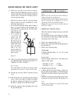
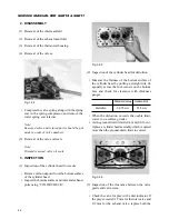
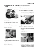
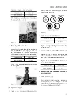
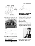
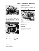
(15) Removal of the flywheel.
• Chock the flywheel.
• Removal of the flywheel.
Fig. 3-60
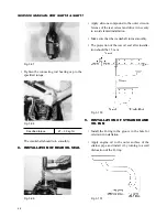
(16) Remove the rear plate.
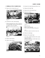
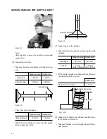
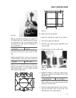
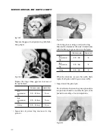
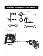
(17) Removal of the crankshaft.
• Remove bearing caps.
Fig. 3-61
• Put aside removed bearing caps and bearings in
order of bearing numbers.
• Remove the crankshaft.
(18) Remove the oil pressure switch.
3.
INSPECTION OF CYLINDER BLOCK,
CRANKSHAFT, CAMSHAFT, AND
TAPPETS
(1) Inspection of the cylinder block
• Inspect the cylinder block for damage.
Check for damage visually.
Use “COLOR CHECK” if necessary to check
for cracks and other damage. Repair damage if
possible or replace.
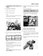
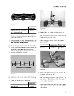
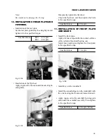
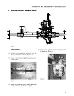
• Inspect the cylinder block top surface for flat-
ness.
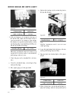
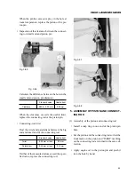
Check the top surface for distortion with a
straight rule and thickness gauges in diagonal
ways as shown in the figure.
Fig. 3-62
Standard value
Usable limit
0.08 mm
0.15 mm
or less
If distortion exceeds the usable limit, correct on
a surface grinder. But the ground-down limit is
0.4 mm. A cylinder block which cannot be cor-
rected within the ground-down limit should be
replaced with a new one.
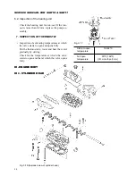
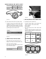
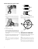
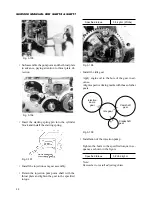
• Check the cylinder bores for wear.
Summary of Contents for SCM49
Page 1: ...S E R V I C E M A N U A L I S E K I L A W N M O W E R S LAWN MOWERS MOWER DECKS SCM48 SCM54 ...
Page 7: ...7 CHAPTER 1 INTRODUCTION 3 EXTERIOR VIEW AND DIMENSIONS 1935 mm 1965 mm 1100 mm 1265 mm ...
Page 36: ...36 SERVICE MANUAL FOR SGR19 SGR17 Fig 3 55 III 3 CYLINDER BLOCK 1 EXPLODED VIEWS ...

