41
ISEKI LAWN MOWERS
oil clearance again. When the clearance exceeds
the usable limit ever after new bearing have been
installed, polish the pin and use undersize bear-
ings.
Undersize bearings
0.5; 1.0 mm
When the ground-down limit of 1.0 mm (0.039
in.) is enough for correction, replace both crank-
shaft and bearings with new ones.
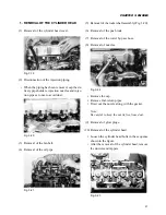
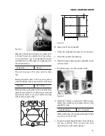
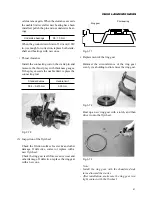
• Thrust clearance
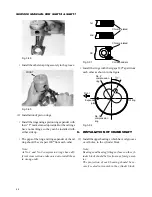
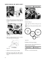
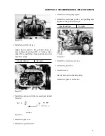
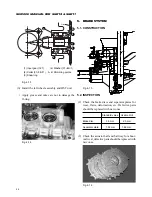
Install the connecting rod on the crank pin and
measure the thrust play with thickness gauges.
If the play exceeds the usable limit, replace the
connecting rod.
Standard value
Usable limit
0.04 – 0.215 mm
0.30 mm
Fig. 3-70
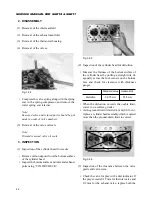
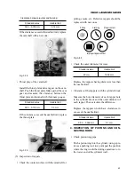
(3) Inspection of the flywheel
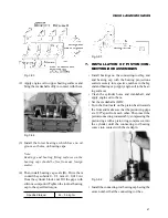
Check the friction surface for cracks and other
damage. If defective, correct or replace with a
new flywheel.
Check the ring gear teeth for excessive wear and
other damage. If defective, replace the ring gear
with a new one.
Fig. 3-71
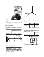
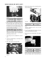
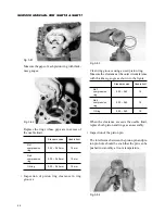
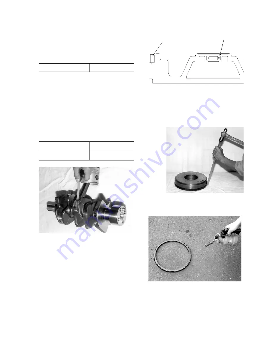
• Replacement of the ring gear
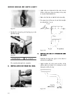
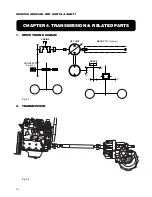
Hammer the circumference of the ring gear
evenly via a holding rod to remove the ring gear.
Ring gear
Pilot bearing
Fig. 3-72
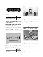
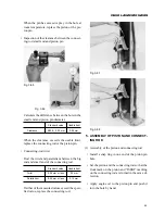
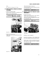
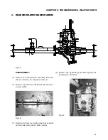
Heat up a new ring gear with a torch, and then
drive it onto the flywheel.
Fig. 3-73
Note:
- Install the ring gear with the chamfered side
turned toward the starter.
- After installation, make sure the ring gear is in
tight contact with the flywheel.
Summary of Contents for SCM49
Page 1: ...S E R V I C E M A N U A L I S E K I L A W N M O W E R S LAWN MOWERS MOWER DECKS SCM48 SCM54 ...
Page 7: ...7 CHAPTER 1 INTRODUCTION 3 EXTERIOR VIEW AND DIMENSIONS 1935 mm 1965 mm 1100 mm 1265 mm ...
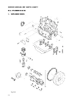
Page 36: ...36 SERVICE MANUAL FOR SGR19 SGR17 Fig 3 55 III 3 CYLINDER BLOCK 1 EXPLODED VIEWS ...

