53
CHAPTER 4. TRANSMISSION & RELATED PARTS
3.
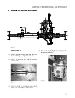
REAR WHEEL DRIVING MECHANISM
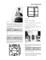
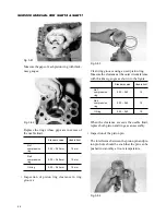
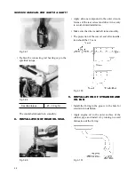
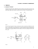
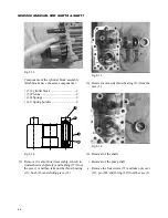
Fig. 4-3
DISASSEMBLY
(1) Remove the transmission assembly from the
chassis, referring to component removal.
(2) Remove the left wheel shaft from the transmis-
sion assembly.
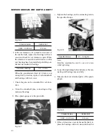
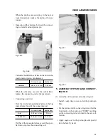
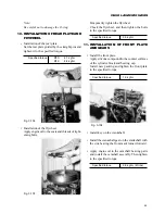
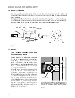
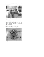
Fig. 4-4
(3) Remove the brake cover tightening bolts and pull
out the parts related to the brake system.
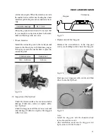
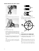
(4) Remove the tightening bolts and separate the
transmission assembly.
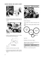
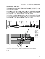
Fig. 4-5
Summary of Contents for SCM49
Page 1: ...S E R V I C E M A N U A L I S E K I L A W N M O W E R S LAWN MOWERS MOWER DECKS SCM48 SCM54 ...
Page 7: ...7 CHAPTER 1 INTRODUCTION 3 EXTERIOR VIEW AND DIMENSIONS 1935 mm 1965 mm 1100 mm 1265 mm ...
Page 36: ...36 SERVICE MANUAL FOR SGR19 SGR17 Fig 3 55 III 3 CYLINDER BLOCK 1 EXPLODED VIEWS ...

