background image

TH4330,4290,4260

42

STOPPING TRACTOR (Hydrostatic Transmission)

FIG. 5-12: To stop Tractor with hydrostatic transmission,
move hydrostatic control lever (TH4330/4290), 1, slowly
to “0” position, or, if using forward pedal, 2, and lever is
located in “0” position, release pedal to stop.

Move throttle lever, 3, forward to reduce engine speed.
Depress brake pedal firmly and set parking brake, 4, and
move range shift lever, 5, to neutral position.

CAUTION: Never start traveling with the park-
ing brakes applied, brake performance will be
effected as they heat up.

Allow engine to idle several minutes to allow even cool-
ing, then turn main switch to "off position" shutting off
engine. Lower three-point hitch and remove key from
main switch.

FIG. 5-13: Always park Tractor on level area when-
ever possible. If hillside parking is necessary, securely
block both rear wheels as shown.

CAUTION: Before leaving Tractor unattended,
make sure brakes are locked, rear mounted
implement is lowered to the ground and key
is removed from the ignition.

DIFFERENTIAL LOCK OPERATION

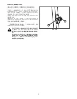
FIGS. 5-14 & 5-15: Differential lock lever or pedal,
1,should only be lowered when required as steering abili-
ty is greatly reduced.

To engage differential lock, allow all rear wheel move-
ment to stop. Lower lock lever or pedal.

To disengage differential lock, release differential lock
lever or pedal. Lock lever or pedal should normally return
to the "off" position;

CAUTION: DO NOT use differential lock on
hard surfaces or when transporting unit. DO
NOT, engage with rear wheel(s) spinning as
severe damage may result.

FIG. 5-12

FIG. 5-13

FIG. 5-14 (Mechanical Transmission)

FIG. 5-15 (Hydrostatic Transmission)

Summary of Contents for TH4260

Page 1: ...ine He will discuss with you the operating and maintenance instructions gives in this manual and instruct you in the proper and varied applications of this machine Call on him at any time when you have a question or need equipment related do the use of your machine Paragraphs in the manual and labels on the machine which are accompanied by a caution particularly important information about safe op...

Page 2: ...ION SHIFT LEVER AND CONTROLS Mechanical Transmission 30 TRANSMISSION SHIFT LEVER AND CONTROLS Hydrostatic Transmission 31 Range Gearshift Lever 31 Hydrostatic Control Lever 31 Hydrostatic Control Pedals 31 Control Lever Positions 31 Mechanical Transmission DIFFERENTIAL LOCK LEVER 32 FOUR WHEEL DRIVE SHIFT LEVER 32 REAR PTO SELECTOR LEVER 32 MID PTO SELECTOR LEVER 32 Hydrostatic Transmission DIFFER...

Page 3: ...DJUSTMENT Mechanical Transmission 74 BRAKE ADJUSTMENT 74 HYDROSTATIC ADJUSTMENTS 76 WHEELS TIRES 76 Tire Inflation Pressure 76 Wheel Bolt Torque 76 Front Wheel Alignment 76 Front Wheel Spacing 77 Rear Wheel Spacing 77 Steering Free Play 78 Front Axle End Float 78 CLUTCH HOUSING PLUG 78 TORQUE CHART 78 STORAGE 79 7 TROUBLESHOOTING 80 ENGINE 80 BRAKE 81 HYDRAULIC SYSTEM 81 STEERING SYSTEM 81 ELECTRI...

Page 4: ...ng and after operation and never take chances MAKING YOUR TRACTOR A SAFE VEHICLE HOW TO MAINTAIN SAFETY 1 Never attempt to do the following Modification of the structure of the tractor Installation of other type engine Installation of tires of other than the original tire size Any malfunctions or failures of the tractor due to unauthorized modification are not covered by the war ranty 2 This machi...

Page 5: ...reaks 3 Wear appropriate clothing and other protective devices during operation Protection of your head Wear protective headgear such as a helmet espe cially when traveling on roads or handling material above your head Protection to avoid being caught in the machine Wear tight fitting clothing and headgear because loose clothing or hair can get caught in the moving parts of the machine Protection ...

Page 6: ...er servicing 4 Never inject fuel while the engine is running or is still hot Keep away from open fires an never smoke around a fuel tank or while fueling into the machine Never use open flames for illumination when fueling the machine at night STARTING ENGINE AND MOVING TRACTOR 1 Before starting the engine indoors make sure that there is proper ventilation because exhaust fumes contain poisonous c...

Page 7: ...he engine brake effectively 5 When traveling on a road where one or both shoul ders are slanted and which run along a ditch look out for softened shoulders especially when the ditch is full of water and be careful not to let the machine slip sideway 6 Never allow other persons to get on the machine or the implement except when the machine or the imple ment is provided with a seat or a platform for...

Page 8: ...vel and unloading it in forward travel 4 Never depress the brake pedal during loading or unloading operation or the tractor may shift side ways which may cause it to fall of the ramps 5 If the engine stalls unexpectedly on the ramps depress the brake pedal immediately and roll the trac tor to the ground by manipulating the brake pedal Start the engine on the ground and try again 6 When the machine...

Page 9: ...drive the tractor slowly and straight so that it dose not slip or turn over 4 Do not touch dangerous parts such as rotating parts moving parts hot parts muffler radiator or engine etc or electric parts battery terminals and other live parts or you may be injured seriously 5 If you use a trailer use a proper one which suits your tractor Using an improper trailer may cause serious accidents Never at...

Page 10: ...cap while the engine is hot or running Wait until the engine cools down and then relieve the radiator pressure by releasing the radiator cap Carelessly pouring cooling water into the heated radiator can cause serious damage to the radiator and the engine Careless removal of the radiator cap can cause serious injury because of overheated water vapour 6 Never fit unauthorized implements or attempt u...

Page 11: ...ersonnel as soon as possible Wear suitable protective clothing gloves eye face protection STORAGE 1 Never cover a hot machine just after operation with a tarpaulin or the like or the heated engine and related parts may cause a fire 2 Before storing the tractor for a long period of time disconnect the battery cables to prevent them in case they are gnawed by a rat from causing a short circuit which...

Page 12: ...pair or replace damaged wiring 4 Remove chaff of dust from the battery wiring muffler or engine Otherwise it could result a fire TO HANDLE THE BATTERY 1 When working around the battery avoid smoking The battery generates explosive hydrogen and oxy gen gases when it is being charged Keep the battery away from sparks or open flames 2 The battery should be inspected before starting the engine Be care...

Page 13: ...lectrical capacity A cable of inadequate capacity will cause generation of heat which may lead to a fire SAFETY DECALS The labels are stuck on the tractor You should of course read the safety instructions in the manual But never fail to read the labels on the machine as well The labels should always be clearly seen that is nothing should obscure them When they have become dirty wash them with soap...

Page 14: ...part warning label Code No 8595 901 007 0 WARNING HOT SURFACES RISK OF BURNS ON HANDS AND FINGERS Stay clear of the heated parts until they cool down sufficiently 5 Ether label Code No 1674 904 002 1 WARNING RISK OF EXPLOSION Ether or other starting fluid should never be used to start engines equipped with glow plugs 6 PTO label Code No 8654 901 002 0 WARNING RISK OF ENTANGLEMENT Stay clear of the...

Page 15: ...TION MANUAL Read the safety and operating instructions in the operation manual before operating the tractor Take care of handling the battery Improper handling may lead to explosion Never short the poles Charge the battery in a well ventilated place 10 Starter warning label Code No 1705 902 007 0 DANGER RISK OF ELECTRIC SHOCK Start the engine only from the seat using the key 11 Operation caution l...

Page 16: ...ing tractor to reverse direction be sure to reduce engine speed 14 ROPS label Code No 1674 904 005 0 WARNING RISK OF INJURY Keep the ROPS in the upright position and fasten the seat belt at all times Do not jump from the seat if the tractor starts to overturn or you could be crushed under the tractor The ROPS should usually be kept in the upright position during operation However when the ROPS has...

Page 17: ...SAFETY 17 LOCATION OF SAFETY DECALS Location of all instruction decals provided as a reference Replace any decals that are damaged missing or are not readable Consult your dealer ...

Page 18: ... of this machine Inexperienced operators should study contents of this publication and receive instruction from an experienced operator when possible Your ISEKI Dealer can also assist in areas concerning machine operation and provide details concerning safe operation it is suggested that this booklet be kept readily accessible preferably with the machine for future reference if questions or concer...

Page 19: ...To ensure prompt efficient service when ordering parts or requesting repairs from authorized Dealer record these numbers in spaces provided TRACTOR MODEL TRACTOR SERIAL NUMBER FIGS 3 1 3 2 Tractor identification plate 1 located below operator s seat on right hand side of fender Contains model number machine series number and weight in addition to Tractor serial number TRACTOR IDENTIFICATION FIG 3 ...

Page 20: ...the injection pump Engine serial number 2 is stamped into cylinder block below engine model number CHASSIS NUMBER FIG 3 4 Chassis number 1 is stamped in right side of front frame NOTE Reference to left hand and right hand used throughout this book refers to the position when seated in operator s seat and facing forward FIG 3 3 FIG 3 4 ...

Page 21: ...Lower Link 6 Rear Wheels 7 Operator s Seat 8 Instrument Panel 9 Steering Wheel 10 Fender 11 Reflector Tail Light 12 Hood 13 Front Grille 14 Battery 15 Front Hitch 16 Engine 17 Foot Step 18 Transmission 19 Front Wheel Drive Shaft 4WD 20 Headlight 21 Front Axle 22 Front Axle Pivot 23 Lift Arm 24 Drawbar 25 Turn Hazard Light 26 Center Housing 27 Lower Link Spring 28 Roll Over Protective Structure ROP...

Page 22: ...ake Off PTO Selector Lever 11 Three Point Hitch Position Control Lever 12 Foot Throttle Pedal 13 Hand Throttle Lever 14 Brake Pedals 15 Draft Control Lever Accessory 16 Auxiliary Hydraulic Valve Controls Accessory 17 Clutch Pedal INSTRUMENTS CONTROLS FIG 4 1 General layout and location of controls within operator s area on Tractor Specific use of these controls is given later in this section and a...

Page 23: ...ft Lever 10 Rear Power Take Off PTO Selector Lever 11 Three Point Hitch Position Control Lever 12 Hydro Forward Reverse Pedal 13 Hand Throttle Lever 14 Brake Pedal 15 Draft Control Lever Accessory 16 Auxiliary Hydraulic Valve Controls Accessory FIG 4 2 General layout and location of controls within operator s area on Tractor Specific use of these controls is given later in this section and also in...

Page 24: ... OFF Engine and all electrical circuits off Key can be removed O ON Power supplied to all circuits Normal operating position G GLOW Energizes glow plugs to preheat the com bustion chambers and assist starting f START Starter activated This position spring located to ON NOTE The main switch must be turned to ON before any circuits will operate PTO switch must be turn off before engine can be starte...

Page 25: ...tes engine coolant temperature when main switch is selected to ON Cold Extreme left Shows too cool temperature for severe work Allow to warm needle in mid position before applying heavy load Hot Extreme right Indicates over heating red area on gauge Reduce engine speed to idle allow to run at no load several minutes shut off engine and investigate cause refer to Troubleshooting CAUTION Do not serv...

Page 26: ...ch 8 Is a rotary switch with three operating positions OFF Fully counterclockwise All lights off 1st Main high beam headlamps and rear tail lights 2nd Low beam headlamps and rear red tail lights NOTE When high beam is selected 1st position light indicator light strip will come on Turn Switch 9 Operate switch handle in direction Tractor is to be turned The appropriate flashing amber warning light f...

Page 27: ...PTO The switch is pushed to disengage PTO IMPORTANT PTO switch is equipped with a lock out to prevent accidental engagement of PTO on switch to unlock AND THEN rotate switch clockwise to ON position DO NOT FORCE SWITCH NOTE PTO switch 1 must be used in conjunction with rear and mid PTO selector lever to left and under operator s seat when rear and mid PTO used Refer to Operation section for comple...

Page 28: ...he PTO drive first which allows the PTO driven machine to get up to speed and then with transmission in gear forward travel will begin as the second stage clutch is released Note Clutch pedal should be depressed quickly to prevent abnormal wear Clutch pedal should be raised smoothly to pre vent sudden movement DO NOT rest your foot on the clutch pedal except when operating the clutch Important Clu...

Page 29: ...ent abnormal brake wear ENGINE SPEED CONTROL Throttle Lever FIG 4 19 Throttle lever 4 controls engine speed and will remain in position selected by the operator Idling speed With hand lever is forward engine will idle High speed Engine speed increases as lever is pulled progressively rearward Hydrostatic Transmisson These tractor is equipped with Auto throttle system it raises up engine speed by d...

Page 30: ...hree major speed changes on TH4290 4260 Main Shift Lever 2 Providers smaller speed changes It has three forward gears and one reverse gear speed change In total nine forward and three reverse gear speeds are possible on TH4290 4260 FIG 4 21 Main shift lever is located at front It has three forward and reverse gear Range shift lever is located at rear It has turtle rabbit 1 and rabbit 2 positions w...

Page 31: ...rd or reverse travel direction Refer to details that follow Hydrostatic Control Pedals FIG 4 23 Depressing left side pedal 4 moves Tractor forward depressing right side pedal 5 moves Tractor rearward As each pedal is progressively depressed a corresponding increase in ground speed of Tractor will be noticed in the appropriate direction Returning pedal towards spring loaded center position will slo...

Page 32: ...apid wear of front tires and possible drive line damage could occur if 4 WD is operated for prolonged periods on hard surface REAR PTO SELECTOR LEVER FIG 4 27 Rear PTO Power Take Off selector lever 3 controls rear PTO on Tractor When lever is rearward 540 rpm rear PTO is selected When lever is returned to forward neutral N position the gear drive is disengaged IMPORTANT Before moving rear PTO is s...

Page 33: ...ar of front tires and possible drive line damage could occur if 4 WD is operated for prolonged periods on hard surface REAR PTO SELECTOR LEVER FIG 4 31 Rear PTO Power Take Off selector lever 3 controls rear PTO on Tractor When lever is rearward 540 rpm and forward 1000 rpm rear PTO is selected When lever is returned to center neutral N position the gear drive is disengaged IMPORTANT Before moving ...

Page 34: ...ol lower draft lever 2 fully and then use position control NOTE When starting engine ensure implement is low ered to the ground and both levers are fully for ward This reduces load on starter due to hitch trying to raise when engine is cranked Lowering Rate Control Knob FIG 4 34 Lowering rate knob 5 adjusts rate of drop of three and implement Turning knob clockwise will increase lowering time and ...

Page 35: ... start up of Tractor a few basic procedures should be followed to ensure Tractor is in operating order to insure life and dependability Make sure all safety shields ate in place and secured properly Make sure operator is instructed on correct and safe operation of Tractor and related attachments or imple ments Check coolant engine oil and transmission oil levels and replenish as necessary Check fa...

Page 36: ...must be in neutral and the PTO levers must be in neutral to actuate safety switches and permit opera tion of the starter motor 5 Set the position control lever 5 three point hitch and draft control lever if equipped in the down position 6 Turn the main switch 7 to the glow position for 5 10 seconds 7 Set the throttle lever 8 at half to the fully open position 8 Turn the main switch 7 to the on pos...

Page 37: ...tely warm engine combustion chambers At temperatures below 39 F 4 C use of No 1 No 1 D diesel fuel is recommended due to possible fuel gelling characteristics of No 2 No 2 D fuel at cold ambient temperature The central hydraulic fluid in addition to transmission and center housing lubrication will require additional warm up time due to cold thicker oil Refer to Warm Up Period at right Test all con...

Page 38: ...ocating problem Starting Circuit Operation Tractor is equipped with a starting system to protect the operator To permit tractor to be started start motor to operate ALL the following is required Mechanical Transmission Gear and Range shift lever in Neutral Rear and Mid PTO shift lever in Neutral Depress clutch pedal Hydrostatic Transmission Range Gear Shift Lever in Neutral PTO control switch in O...

Page 39: ... in desired positions Release parking brake and slowly release clutch pedal If another gear selection is required stop travel and repeat the above operation STOPPING THE TRACTOR Mechanical transmission To stop the tractor with a regular gear transmission move the throttle lever 1 forward to reduce engine speed and slow travel Depress the clutch pedal 2 and brake pedal 3 to stop Position the range ...

Page 40: ...TH4330 4290 4260 40 FIGS 5 8 Arrangenent of gear with appropriate ground speeds in order from slow to fast are shown in the chart below NOTE Ground speed indicated at 2500 engine rpm FIG 5 8 ...

Page 41: ...eutral and Tractor will stop Reverse travel speed is obtained by pushing pedal 4 down As pedal is progressively pushed down a corre sponding increase in ground speed will be noticed When released pedal will return to neutral position FIG 5 11 Arrangement of gear with appropriate ground speeds in order from slow to fast are shown in the chart at right NOTE Ground speed indicated at 2600 engine rpm ...

Page 42: ...h FIG 5 13 Always park Tractor on level area when ever possible If hillside parking is necessary securely block both rear wheels as shown CAUTION Before leaving Tractor unattended make sure brakes are locked rear mounted implement is lowered to the ground and key is removed from the ignition DIFFERENTIAL LOCK OPERATION FIGS 5 14 5 15 Differential lock lever or pedal 1 should only be lowered when r...

Page 43: ...ires This is to assist steering when four wheel drive is selected For this reason front axle must be disengaged when Tractor is transported or operated on a hard dry surface Failure to do so will result in rapid wear of front drive tires and possible driveline damage IMPORTANT Always disengage front drive axle when operating in conditions with minimal wheel slippage DRY OR HARD SURFA CES If tire r...

Page 44: ...mple ment drawbar as a step NEVER use the driveline as a step NEVER wear loose fitting clothes Keep at least your height away from a rotat ing driveline Rear PTO Shaft FIG 5 19 A six spline 1 3 81 35 mm PTO shaft 1 is provided at rear of Tractor to provide power for mounted and other PTO driven equipment as required A protective cover is positioned over shaft splines when not in use Normal rear PT...

Page 45: ...anical Transmission FIG 5 22 These tractors have a dual clutch To select the rear PTO push the clutch pedal completely down to disengage drive to PTO drive train Allow time for drive train to stop and then move lever 2 at the left of the seat to the 540 rpm position To engage the PTO slowly release the clutch pedal through the first stage then increase engine speed to obtain 540 PTO rpm With the P...

Page 46: ...is OFF and then move mid PTO selector lever 3 upward to engage gear set inside rear housing To engage PTO Push PTO control switch 1 and then rotate clockwise to actuate hydraulic clutch and complete the drive To disengage PTO Push PTO control switch 1 to release hydraulic clutch NOTE Push knob in and then rotate switch clockwise to prevent switch damage Do not force PTO switch to ON position Reduc...

Page 47: ...draft or pull of ground engaging implements plows subsoil s etc Moving draft control lever 2 forward will provide deeper implement working depth Moving lever rearward will provide a shallower depth As ground contours and or soil conditions change the system will raise or lower implement as needed to keep even load on Tractor CAUTION Use position control lever 1 when attaching or detaching implemen...

Page 48: ...ch varying implements rear linkage is standardized according to spacing pin size etc This enables usage of alternate implements with minimal adjustments as long as matching size or Category of implement is used This Tractor is equipped for Category I implements with following attaching point dimensions FIG 5 31 Linkage provides two positions of connecting top link to Tractor For most implements se...

Page 49: ...ing turn buckle 2 Attach and secure right lower link 3 to implement with lynch pin Attach top link 4 to top of implement hitch frame using pin supplied with Tractor Rotate center barrel section of top link to lengthen or shorten and level implement from front to rear After the implement is attached adjusted for level opera tion as needed using lift rod and top link turn buckles Secure all adjustme...

Page 50: ...lement in field and move position control lever 1 forward toward DOWN Adjust implement height using position control lever and sent adjustable stops 3 and 4 as desired When Turning Move position lever 1 rearward toward UP to raise implement Finish turning and return lever against stop to resume operation To Finish Work and Transport Move position control lever 1 fully rearward in quadrant FIG 5 36...

Page 51: ...s To Begin Work Align Tractor and implement in field and move position control lever 1 forward to DOWN while driving Tractor forward lowering implement Then adjust draft control lever 2 until correct working depth is maintained When Turning Move position control lever 1 rearward to raise implement and permit completion of turn Return implement to work position by selecting position control lever p...

Page 52: ...re interference Take position in operator s seat start engine and drive Tractor clean of implement EXTERNAL AUXILIARY HYDRAULICS ACCESSORY Auxiliary hydraulics can be Dealer installed to operate implements requiring external hydraulic source for opera tion Kits are available as single spool one auxiliary cir cuit or two spool two spool kit only FIG 5 40 Control lever 1 controls implement raising l...

Page 53: ...nt cylinder will have two hoses connected to it When single acting service is required cylinder with only one hose the inner coupler 1 will be used and selector function 2 located at right rear of tractor must be turned to the left NOTE For normal double acting operation selector function must be turned to the right Disconnect lower links from implement pins Make sure lower links are connected tog...

Page 54: ... time ROPS must be maintained in this fully raised position at all times unless practical operation of the tractor dictates other wise as described above FIG 5 45 Remove linchpin 1 remove pin 2 and tilt the ROPS rearward care fully CAUTION Do not weld drill bend or straight en Make sure all components are in correct working order to provide the intended protec tion Only original bolts or equivalen...

Page 55: ...ter System Capacity 7 1 liters Fuel Tank Capacity 30 0 liters with sub tank 23 0 liters Fuel Recommended Above 40 C No 2 or No 2 0 Fuel Recommended Below 40 C No 1 or No 1 D Transmission Differential Housing Including Hydraulic System Capacity 29 0 liters Recommended Lubricant Shell DONAX TD Recommended Change Interval First 50 hours every 200 hours thereafter Front Axle 4WD Capacity 4 5 liters Re...

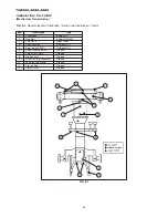
Page 56: ...ef Description Type 1 Crankcase Engine Oil 2 Radiator Engine Coolant 3 Fuel Tank Diesel Fuel 4 Rear Housing Hydraulic Oil 5 Front Axle 4 WD Hydraulic Oil 6 Power Steering Rod Grease 7 Axle Pivot Points Grease 8 Brake Pivots Grease 9 Draft Pivots Accessory Grease 10 Levering turnbuckle Grease 11 Tie rod End Grease 12 Clutch Pivot Grease FIG 6 1 ...

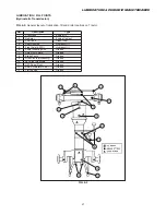
Page 57: ...tion Type 1 Crankcase Engine Oil 2 Radiator Engine Coolant 3 Fuel Tank Diesel Fuel 4 Rear Housing Hydraulic Oil 5 Front Axle 4 WD Hydraulic Oil 6 Power Steering Rod Grease 7 Axle Pivot Points Grease 8 Brake Pivots Grease 9 Draft Pivots Accessory Grease 10 Levering turnbuckle Grease 11 HST Pedal Pivot Grease 12 13 Auto Accelerator Pivot Tie rod End Grease Grease FIG 6 2 ...

Page 58: ...h Items marked indicate initial service interval only Subsequent later intervals marked 0 Intervals above are for normal usage Severe operating conditions wet dusty etc or when previous servicing has indicated need for more frequent action intervals may need to be more often ...

Page 59: ...red prior to operating unit To access radiator battery and engine components top of engine bonnet can be opened both hood side panels and front grill can be easily removed FIGS 6 3 6 4 To open turn locking knob 1 one quarter turn clockwise on top of engine bonnet pull upward the bonnet and lock it by retaining stay 2 Reinstall in reverse order engine bonnet will be nec essary to push inward on loc...

Page 60: ... 6 7 To remove front grill unscrew locking knobs 4 and pull upward and outward to remove Disconnect headlights wiring couplers 5 Reinstall in reverse order making sure front grill lower projections engage on holes FIG 6 6 FIG 6 7 ...

Page 61: ... through dipstick filler opening as required WARNING Muffler tail pipe is extremely hot just after operation take care not to touch it to avoid burns when checking engine oil level FIG 6 9 To add oil remove filler cap 2 and pour oil using a funnel to prevent oil from spilling NOTE Add oil slowly to assist in venting air from crankcase FIG 6 10 To Change Engine Oil Operate Tractor until oil is adeq...

Page 62: ...each axle Completely drain oil from system IMPORTANT Completely lower three point hitch prior to draining transmission oil When completely drained replace and tighten all drain plugs Service hydraulic and hydrostatic filters as required and then refill with oil FIG 6 14 Transmission filter 5 must also be cleaned when oil is replaced With oil drained Remove retaining bolt 6 withdraw filter from lef...

Page 63: ...to bleed the hydraulic system can cause pump seizure and or poor hydraulic system performance Front Axle Oil Front drive axle has a common oil level for front differen tial housing and each wheel reduction unit Oil level should be checked every 50 hours of Tractor operation The oil should be changed after the first 50 hours or oper ation and then replaced after every 300 hours thereafter FIG 6 18 ...

Page 64: ...T Use care when cleaning radiator to pre vent cooing fin damage FIG 6 20 Drain cock 2 will drain coolant from cylinder block and radiator Drain cock is located on right side of engine Coolant should be replaced if it becomes contam inated with rust or sludge Loosening radiator cap will assist draining NOTE When coolant is replaced flush inside of radiator and engine block with clean water Radiator...

Page 65: ...ng FIG 6 24 Release clip 3 and remove element 4 Examine element and seals for damage and brittleness If element is damaged in any way it must be replaced NOTE Engine air filter has a seal ring Fit it correctly when reinstalling FIG 6 25 Element 4 may be cleaned if in serviceable condition using following procedures Using compressed air not to exceed 30 psi 200kPa from inside element remove loose d...

Page 66: ... of engine and is used to strain impurities from fuel before fuel reaches injection pump Fuel filter incorporates valve 2 to aid in filter servicing Check filter bowl for accumulation of sediment or water and clean as required FIG 6 27 To replace fuel filter element or clean sedi ment bowl turn fuel valve to OFF position handle to rear Carefully loosen spanner nut 1 and remove nut sedi ment bowl 2...

Page 67: ... of the pump If engine still fails to start pressure injection lines can be loosened where they attach to injectors Turn engine over several times until fuel spurts out then tighten lines and stop engine CAUTION Fuel emitted from injection lines is high pressure Keep hands and face away when engine is cranked Clean all spilled fuel following air bleeding procedure s Throttle Lever FIG 6 30 Hand th...

Page 68: ...furic acid electrolyte fluid Wear eye and face protection lf electrolyte comes in contact with skin or clothes wash immediately Contact physician if electrolyte is ingested or gets in eyes FIG 6 32 Tractors are shipped with battery installed If battery replacement should become necessary discon nect negative cable i first and then remove positive cable 2 Loosen and remove battery securing clamp an...

Page 69: ...le inside indicator Then check battery indicator WARNING Never disassemble battery Batteries contains sulfuric acid electrolyte fluid Keep away from sparks or flames which could cause explosion When charging battery from an external source Set charging voltage below 16v Set charging ampere below 1 10 one tenth of battery capacity When connecting and disconnecting battery cables turn off power of b...

Page 70: ...safety features of the system CAUTION Tractor is equipped with negative ground system Tractor metal parts pro vide many electrical connections For this reason all positive circuits must be insu lated to prevent grounding or short circuits and prevent possible fire CAUTION DO NOT replace any fuse with a fuse of higher amperage rating DO NOT use wire or foil to bypass fuse protection Fire can result...

Page 71: ...FIG 6 34 1 2 3 4 General layout and location of electrical system components and fuses Main Fuse Box A Located at right side of engine LUBRICATION PERIODIC MAINTENANCE 71 FIG 6 34 1 FIG 6 34 2 ...

Page 72: ...TH4330 4290 4260 72 FIG 6 34 3 FIG 6 34 4 ...

Page 73: ...cated on right side of engine One 40A slow blow fuse C for main circuit is green in color Fuse is located on right side of engine NOTE Failure of fuse C is usually caused from incor rect polarity such as reserved cables when using booster battery Failed fuse will not allow battery to be charged during normal operation IMPORTANT Fuses are of specific amperage capacity for the circuit in which they ...

Page 74: ...al is depressed FIG 6 36 To adjust clutch pedal free play locate the linkage under the left foot step and loosen lock nut 2 right hand thread and lock nut 3 left hand thread Adjust turnbuckle 4 on linkage until free play is correct Lengthening the linkage will increase free play shorten ing the linkage will reduce free play Secure by retightening the lock nuts BRAKE ADJUSTMENT Mechanical Transmiss...

Page 75: ...ad Adjust rod using weld nut 3 so free play is correct for brake pedal 4 Secure lock nuts against turnbuckles 5 Adjust the brake rod of other side Make sure lock nuts are secured when brake adjustment is complete Check operation of parking brakes after adjustment is made CAUTION Brakes must be adjusted evenly to permit equal braking action at both rear wheels FIG 6 40 After brake system has been a...

Page 76: ...odically check all wheel bolt torques Correct bolt torques Front Wheel Bolts 1 75 ft lbs 102N m Rear Wheel Bolts 2 80 ft lbs 120N m CAUTION Correct wheel bolt torque must be maintained Installation of front mounted implements ex loaders mowers impose increased loads and require frequent check ing of wheel bolts Front Wheel Alignment FIG 6 43 Correct toe in dimension of front wheels A minus B is 0 ...

Page 77: ...recheck after short period of operation NOTE Agricultural lug type tires must always be installed so when viewed from the rear the V pattern of the tread points upward FIG 6 45 Rear tire tread widths FIG 6 44 FIG 6 45 Front Tire type Mechanical Ag Tires Turf Tires Wide Turf Tire Narrow Agri Tire Oversize Agri Tire Tread Width mm A 960 1067 1115 960 990 B Not Recommended Not Recommended Not Recomme...

Page 78: ... its supports should be 0 004 0 012 0 1 0 3 mm End float is measured with axle raised off ground Loosen lock nut 2 and turn adjusting bolt 3 as needed to achieve correct measurement Tighten lock nut NOTE Excessive end float will cause noise This noise will be more pronounced when using 4WD CLUTCH HOUSING PLUG FIG 6 48 Pipe plug 1 should be removed from bottom of clutch housing once a year or when ...

Page 79: ... to prevent condensation from forming on inside of tank Turn filter valve 2 to OFF position 8 Remove battery and store in cool dry place Maintain charge during storage period 9 If Tractor is stored during cold weather season insure that antifreeze is adequate Alternatively radiator and engine block may be drained 10 Check with your diesel fuel supplier on the availability of a diesel fuel additive...

Page 80: ...t your dealer Consult your dealer Engine stops unexpectedly during operation Insufficient fuel supply Defective fuel injectors Defective fuel injection pump Engine seizure due to low or poor oil Electric fuel pump not operating Fill tank and air bleed fuel system Consult your dealer Consult your dealer If engine can be turned by pulling fan belt fuel system is most probable causes Replace fuse Eng...

Page 81: ...oose steering or ball joints Defective steering unit pump Worn steering column Loose ball joints Defective steering unit Correct Air bleed steering system Correct Inflate both tires to same specified pressure Retighten or replace defective parts Consult your dealer Consult your dealer Retighten Consult your dealer Problem Possible Cause Remedy Battery cannot be charged Head lamps are dim Particula...

Page 82: ...ry Infinite Control Range 3 speeds constant mesh Gear Speeds 3 gears forward 3 reverse Clutch None Brakes Mechanically actuated sealed wet disk POWER TAKE OFF PTO Type Independent engine driven Control Electro hydraulic control Clutch Hydraulically engaged multi plate wet disk Rear PTO Shaft 35 mm diameter six spline Output Clockwise rotation Engine Speed engine rpm 581 1050 2500 rpm 604 1092 2600...

Page 83: ...nkcase with Filter 3 6 liters 4 4 liters Transmission 29 0 liters Fuel Tank 23 liters 30 liters TREAD WIDTH SETTINGS Front 4WD Turf Tires 24 x 8 50 12 980 mm Wide Turf Tires 26 x 12 00 12 985 mm Ag Tires 6 14 880 mm Rear 4WD Turf Tires 315 80D 16 945 mm Wide Turf Tires 13 6 16 1040 mm Ag Tires 9 5 22 875 mm MAXIMUM AXLE LOADING Front Axle 875 kg Rear Axle 1000 kg Cooling system Front Drive Axle 7 ...

Page 84: ...t 6 14 Rear 9 5 22 1420 mm 2395 mm 245 mm TH4290 Turf Tire Front 24 x 8 50 12 Rear 315 80D 16 1370 mm 2350 mm 200 mm Wide Turf Tire Front 26 x 12 00 12 Rear 13 6 16 1425 mm 2400 mm 250 mm Agri Tire Front 6 14 Rear 9 5 22 1420 mm 2395 mm 245 mm TH4330 Turf Tire Front 24 x 8 50 12 Rear 315 80D 16 1370 mm 2350 mm 200 mm Wide Turf Tire Front 26 x 12 00 12 Rear 13 6 16 1425 mm 2400 mm 250 mm Agri Tire ...

Page 85: ...verse with 3 speed range Gear Speeds 9 gears forward 3 reverse Clutch Dual clutch φ215 mm Brakes Mechanically actuated sealed wet disk POWER TAKE OFF PTO Type Transmission driven Control Sliding gear and disk clutch Rear PTO Shaft 35 mm diameter six spline Output Clockwise rotation Engine Speed engine rpm 581 2500 rpm Mid PTO Shaft 25 4 mm diameter fifteen spline 25 4 mm diameter fifteen spline Ou...

Page 86: ...12 Narrow Agri Tire 6 14 Oversize Agri Tire 7 14 Rear 4WD Ag Tires 12 4 16 Turf Tires 315 80D 16 Oversize Turf Tire 13 6 16 Narrow Agri Tire 9 5 22 Oversize Agri Tire 9 5 24 MAXIMUM AXLE LOADING Front Axle Rear Axle TH4260F TH4290F 12 volt negative ground 433 cca 40 amp alternator with internal regulator rectifier 3 6 liters 29 0 liters 23 liters 30 liters 7 1 liters 4 5 liters 960 mm 1067 mm 1115...

Page 87: ...m front wheel 1410 mm rear wheel 1340 mm front wheel 1480 mm front wheel 1225 mm winker 1260 mm front wheel 1410 mm rear wheel 2920 mm 1665 mm 225 mm under mid PTO case 200 mm under mid PTO case 250 mm under mid PTO case 245 mm under mid PTO case 270 mm under mid PTO case 225 mm under mid PTO case 200 mm under mid PTO case 250 mm under mid PTO case 245 mm under mid PTO case 270 mm under mid PTO ca...

Page 88: ...t of components wheels fenders ROPS etc that may be attached to or held in position by container panels 1 Remove wheels fenders and sundry boxes from container 2 Disassemble container 3 Inspect Tractor for damage and any evidence of coolant fuel or lubricant leaks 4 Inspect and remove all hardware securing Tractor to lower crate panel 5 Left Fender a Remove tie strap holding control levers b Insta...

Page 89: ...r spring will locate at underside b Connect clevis end of check chains to axle brack ets and secure with clevis pin and cotter pin c Remove bolts at lower end of lift links and attach lift links to identical positions on lower links using bolts lock washers and nuts removed Lift link with turnbuckle adjustment is located on right side IMPORTANT Bolts should be installed with heads to out side nuts...

Page 90: ...ll throttle and turn main switch counterclockwise 5 10 Turn main switch clockwise to ON Oil pressure and alternator warning lights will illuminate Hold in ON position 1 2 seconds Turn main switch to START to crank the engine Release key to ON position the moment engine starts Check that warning lights go out Allow engine to warm up to operating temperature at about 1500 rpm Operate Tractor to conf...

Page 91: ...ISEKI TRACTOR 91 ...

Page 92: ...TH4330 4290 4260 92 ...

Page 93: ...WIRING DIAGRAM WIRING DIAGRAM WIRING DIAGRAM TH4260F ...

Page 94: ...WIRING DIAGRAM TH4260FH ...

Page 95: ...WIRING DIAGRAM TH4290F ...

Page 96: ...TH4330 4290 4260 WIRING DIAGRAM TH4290FH 4330FH ...

Reviews: