44
TXG23
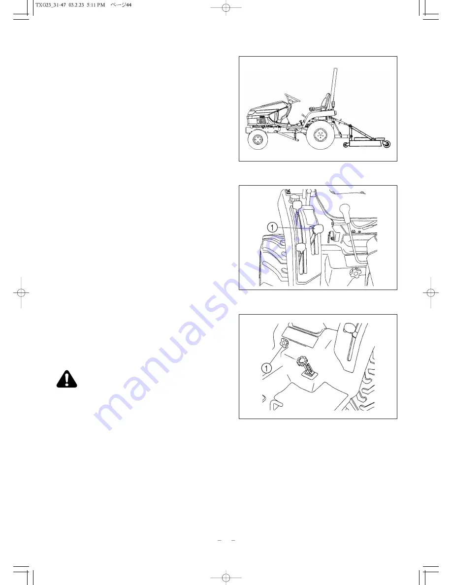
Using Position Control (4WD model)
FIG. 48: Type of Work - Attaching/detaching implements
and other operations requiring implement to be kept at
constant height above ground. Also used with implements
equipped with gauge (support) wheels.
FIG. 49: Lever Positions - Use position control lever, 1,
to adjust hitch and implement position.
To Begin Work - Align Tractor and implement in field and
move position control lever, 1, forward (toward DOWN).
Adjust implement height using position control lever as
desired. Note location of lever.
When Turning - Move position lever, 1, rearward (toward
UP) to raise implement. Finish turning and return lever to
previously set position to resume operation.
To Finish Work and Transport - Move position control
lever, 1, fully rearward in quadrant.
Fig. 50: When using different weights of implements,
"rate of drop" of three point linkage and implement can be
controlled with the "Lowering Rate Control" Knob, 1.
Turn knob clock wise to slow drop rate, counterclockwise
to increase drop rate. Turning knob fully clockwise will
lock implement in raised position.
CAUTION: When using mounted implements
with the PTO driveline, make sure:
PTO drive shaft has minimum 51mm(2")
engagement of telescoping sections, at all
hitch/implement positions.
Hitch height during raising does not bind
drive shaft universal joints due to extreme
drive shaft length,
PTO drive is disengaged during transport.
FIG. 48
FIG. 49
FIG. 50


