16
-
20
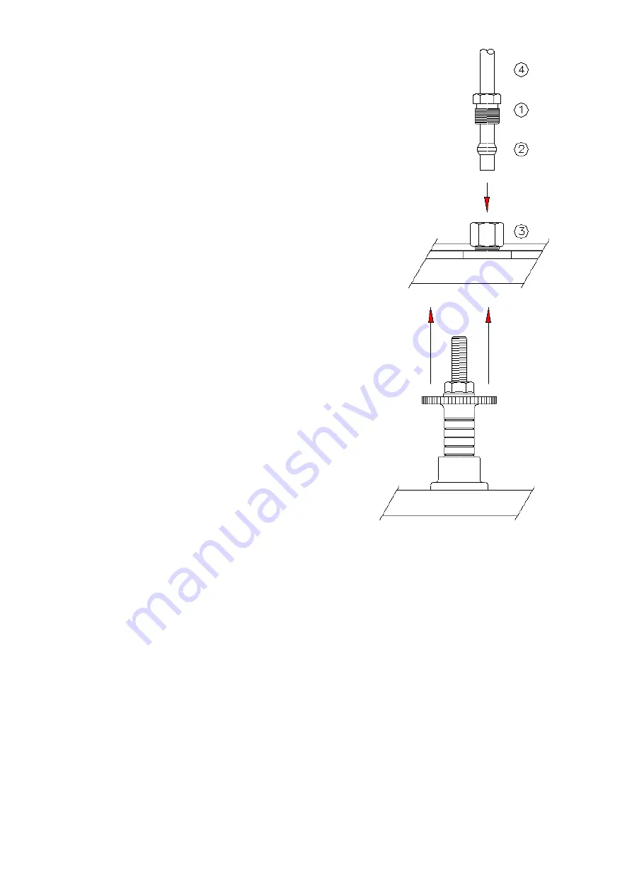
2-4.3 Lubrication line connection
(See Fig. 4)
Solderless tube connection (double
tapered sleeves) can be used. The tube must go through
compressed bushing (1) and double tapered sleeve (2).
To avoid any leaking during running service time, it
should be observed up to 1mmdistance between the tube
end to the double sleeve. Insert tube end into
counterbored port (3) up to the stop. First tighten
compressed bushing finger-tight by hand. Then turn
another 1
1
/
2
turns.
Fig. 4
2-4.4
Manual pump
Pull the regulating plate to the top and let it return
to the original place. In this process, the lubricant is
conveyed to the lubrication line.
Warning!
Don’t press the regulating plate
back. The regulating plate must return by
spring-loaded force.
Fig. 5
2-4.5
Wiring and alarm
Warning !!
To prevent chance of serious injury, death or property damage,
disconnect the product from main power supply before working on it.
The electrical circuit diagram of the lubrication unit is affixed inside the unit and can
be accessed by removing the cap.
Remove the cap (Fig.6) and inside you can see terminal plate and cable gland nut.
Loosen cable gland and then insert cable through the cable gland hole (Fig. 7) to wire
up(Fig. 8). Fix the cable gland to the housing.
Wiring must comply with the electrical circuit diagram (Fig.8) of the lubrication unit
affixed inside the unit.
Otherwise, property damage or serious injury can occur.
Install a fuse between the power supply and the product to protect the lubrication unit
is strongly recommended! Current of fuse, max : 220V 0.3A ; 110V 0.1A


