3 - 8
BC-3000
•
Service Manual
•
Rev. 1
Chapter 3. Parts Disassembly & Replacement
3.5 LOAD CELL REPLACEMENT
1. Remove the upper cover.
Refer to Section 3.2 of this manual for upper
cover removal procedure.
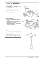
2. Remove the load cell unit.
1) Remove the three screws which secure
the load cell unit.
2) Remove the load cell unit.
3. Remove the A/D board.
1) Remove the screw which secures the A/D
board.
2) Slide the A/D board from its plastic bracket
and disconnect Connector A.
3) Remove the load cell output cable
(soldered in five places).
CAUTION!
•
The load cell output cable has five soldered
points. When replacing be sure that the wires
are in the correct order.
•
After replacing the load cell unit, perform a four-
corner test. (Reference: Section 5.5 of this
manual)
Summary of Contents for BC-300
Page 1: ...SERVICE MANUAL Manual No 0141A ISHIDA CO LTD Retail Scale BC 3000 48775 ...
Page 4: ...HARDWARE SECTION ...
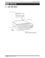
Page 5: ...BC 3000 Service Manual Rev 1 1 1 Chapter 1 Introduction 1 INTRODUCTION 1 1 MAIN COMPONENTS ...
Page 32: ...6 4 BC 3000 Service Manual Rev 1 Chapter 6 Troubleshooting ...
Page 33: ...SOFTWARE SECTION ...
Page 62: ...APPENDIX ...
Page 63: ...BC 3000 Service Manual Rev 1 Appendix 1 Appendix A1 DC DC Converter Unit Schematic Diagram ...
Page 64: ...Appendix 2 BC 3000 Service Manual Rev 1 Appendix ...
Page 65: ......
Page 69: ...Appendix 8 BC 3000 Service Manual Rev 1 Appendix Sample Labels ...
Page 71: ...Appendix 10 BC 3000 Service Manual Rev 1 Appendix Sample Labels ...

