5 - 4
BC-3000
•
Service Manual
•
Rev. 1
Chapter 5. Thermal Head
ADJUSTMENT METHOD
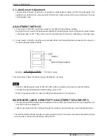
1) In test mode 4 (C04-00), check the values for the label and gap between labels.
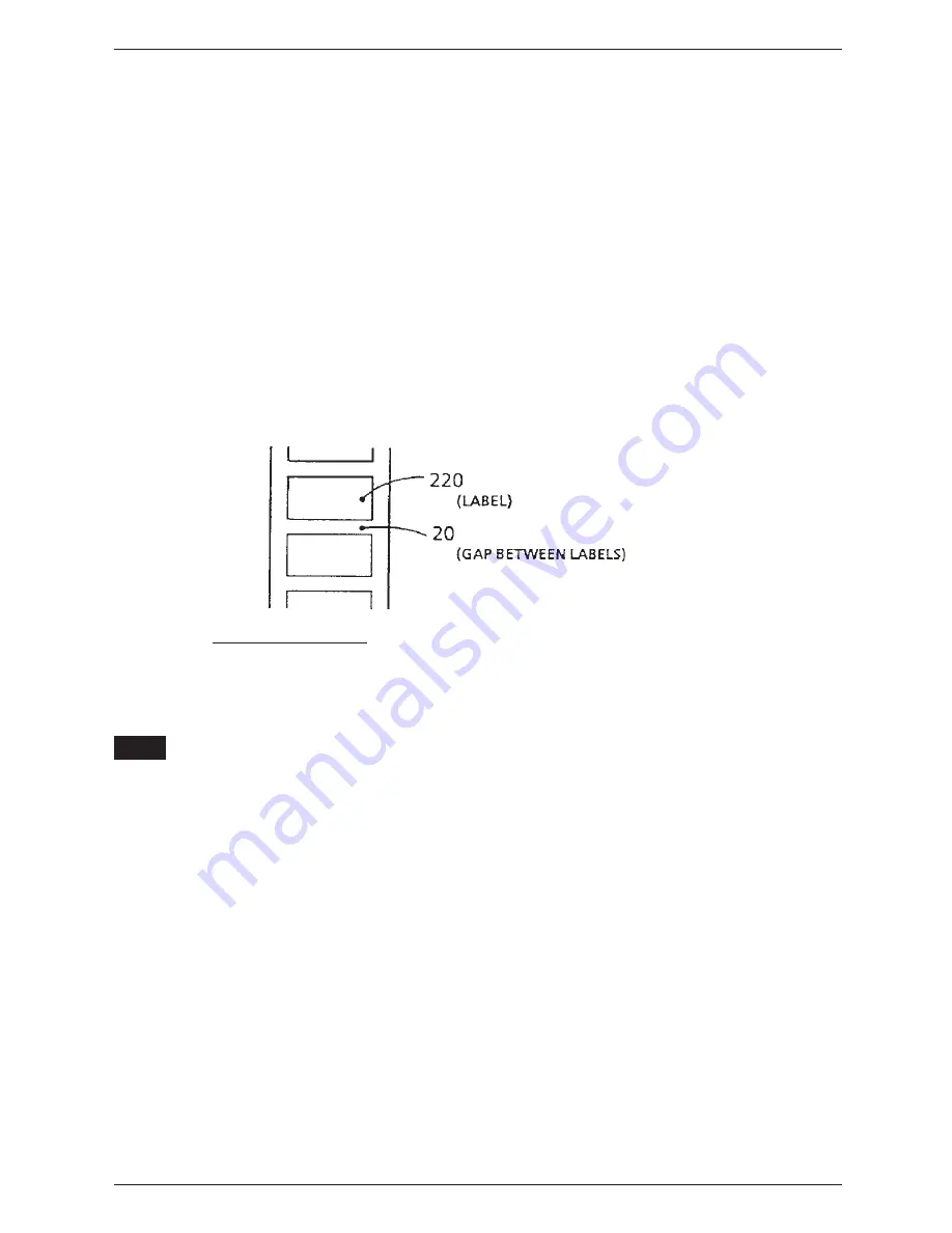
Example: Sensor value for the gap between labels is 20 (backing paper only) and the sensor value for label
on backing paper is 220. These values are for example only and will vary depending on the label type.
2) In test mode 3 (C03-04), input the value calculated from the formula listed below based on the values for
the label and gap between labels.
220* (label) - 20 (gap)
2
This input value (100) is the label and gap identification set value.
•
If label on backing paper value is less than 200, perform adjustment procedure described below.
•
The label and gap identification default setting value is 100.
•
When using receipt paper for report printing, this adjustment is not necessary.
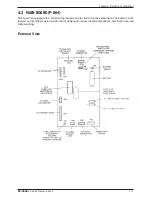
MAIN BOARD LABEL SENSITIVITY ADJUSTMENT VOLUME (VR1)
•
The main board (P-864) label sensor adjustment volume (VR1) generally does not require adjustment (it
is set before factory shipment).
•
Label sensor adjustment is ordinarily through the adjustment method steps 1 and 2 described above.
* The value for label with backing paper must be greater than 200. If the value is less than 200, label feed may
be inconsistent. Ideal value is between 240 and 250.
Note:
Example:
= 100 (input value)
*
2. Label Sensor Adjustment
Label sensing is based on detection of variations in light between labels and the inter-label gaps. This
adjustment is performed to compensate for differences in light values which vary according to the type
of label paper used.
Summary of Contents for BC-300
Page 1: ...SERVICE MANUAL Manual No 0141A ISHIDA CO LTD Retail Scale BC 3000 48775 ...
Page 4: ...HARDWARE SECTION ...
Page 5: ...BC 3000 Service Manual Rev 1 1 1 Chapter 1 Introduction 1 INTRODUCTION 1 1 MAIN COMPONENTS ...
Page 32: ...6 4 BC 3000 Service Manual Rev 1 Chapter 6 Troubleshooting ...
Page 33: ...SOFTWARE SECTION ...
Page 62: ...APPENDIX ...
Page 63: ...BC 3000 Service Manual Rev 1 Appendix 1 Appendix A1 DC DC Converter Unit Schematic Diagram ...
Page 64: ...Appendix 2 BC 3000 Service Manual Rev 1 Appendix ...
Page 65: ......
Page 69: ...Appendix 8 BC 3000 Service Manual Rev 1 Appendix Sample Labels ...
Page 71: ...Appendix 10 BC 3000 Service Manual Rev 1 Appendix Sample Labels ...

