Chapter 4 COMPONENT REPLACEMENT
4-14
BC-4000 Service Manual No. 085-6693-02
4.8
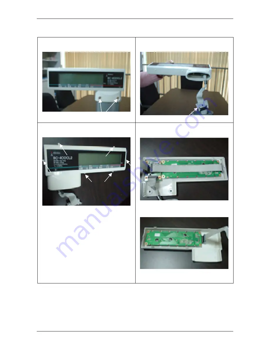
DISPLAY UNIT REPLACEMENT
1. Remove the 2 screws fixing the display unit
with the pole.
2. Pull out the display unit, and remove the flat
cable connector of the display unit.
Screws
Connector
3. Pull out the 6 rubber stopper fixing the
display cover.
4. Open the display cover.
Rubber stoppers
Operator display
Customer display
Summary of Contents for BC-4000
Page 12: ...x BC 4000 Service Manual No 085 6693 02 ...
Page 14: ...Chapter 1 OVERVIEW 1 2 BC 4000 Service Manual No 085 6693 02 1 3 DISPLAY 1 4 KEY SHEET ...
Page 16: ...memo memo memo memo ...
Page 84: ...Chapter 2 SETUP MODE 2 68 BC 4000 Service Manual No 085 6693 02 b01 LABEL FORMAT ...
Page 118: ...memo memo memo memo ...
Page 122: ...memo memo memo memo ...
Page 130: ...Chapter 6 Electric Assembly 6 8 BC 4000 Service Manual No 085 6693 02 ...
Page 131: ...Chapter 6 Electric Assembly BC 4000 Service Manual No 085 6693 02 6 9 ...
Page 132: ...Chapter 6 Electric Assembly 6 10 BC 4000 Service Manual No 085 6693 02 ...
Page 133: ...Chapter 6 Electric Assembly BC 4000 Service Manual No 085 6693 02 6 11 ...
Page 134: ...Chapter 6 Electric Assembly 6 12 BC 4000 Service Manual No 085 6693 02 ...
Page 135: ...Chapter 6 Electric Assembly BC 4000 Service Manual No 085 6693 02 6 13 ...
Page 136: ...Chapter 6 Electric Assembly 6 14 BC 4000 Service Manual No 085 6693 02 ...
Page 137: ...Chapter 6 Electric Assembly BC 4000 Service Manual No 085 6693 02 6 15 ...
Page 138: ...Chapter 6 Electric Assembly 6 16 BC 4000 Service Manual No 085 6693 02 ...
Page 139: ...Chapter 6 Electric Assembly BC 4000 Service Manual No 085 6693 02 6 17 ...
Page 140: ...Chapter 6 Electric Assembly 6 18 BC 4000 Service Manual No 085 6693 02 ...
Page 141: ...memo memo memo memo ...


