Chapter 1 INSTALLATION
IP-EMZ Operation Manual
1-9
7.
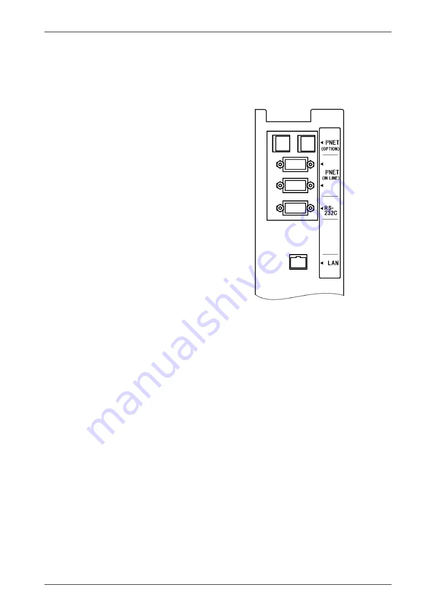
When connecting other devices, connect them according to the following.
Other machine of the master/satellite system I2NET (INLINE) (Dsub 9 pin)
Optional printer ······················································ I2NET (OPTION1) (Modular jack)
IF-21FD ································································· I2NET (INLINE) (Dsub 9 pin)
Journal printer ······················································· RS-232C
8.
Fix the harnesses.
NOTE:
Nylon clamps to fix harnesses are not
attached. Prepare the nylon clamps
beforehand with their sizes according to
the number of the connected harnesses.
Fig.1 Rear Connectors
(Located in the rear cover)
9.
Load labels to be used by the user. Refer to “Label Replacement” in the User’s Manual.
Summary of Contents for IP-EMZ
Page 7: ...Chapter 1 INSTALLATION IP EMZ Operation Manual 1 5 1 3 OUTER DIMENSIONS Unit mm ...
Page 34: ...Chapter 2 NORMAL MODE FUNCTION KEYS page 2 22 IP EMZ Operation Manual ...
Page 35: ...Chapter 2 NORMAL MODE IP EMZ Operation Manual page 2 23 ...
Page 52: ...Chapter 3 TOTAL MODE page 3 16 Omni 4000ST User s Manual ...
Page 58: ...Chapter 4 PROGRAMMING MODE page 4 6 IP EMZ Operation Manual ...
Page 59: ...Chapter 4 PROGRAMMING MODE IP EMZ Operation Manual page 4 7 ...
Page 60: ...Chapter 4 PROGRAMMING MODE page 4 8 IP EMZ Operation Manual ...
Page 62: ...Chapter 4 PROGRAMMING MODE page 4 10 IP EMZ Operation Manual ...
Page 63: ...Chapter 4 PROGRAMMING MODE IP EMZ Operation Manual page 4 11 ...
Page 65: ...Chapter 4 PROGRAMMING MODE IP EMZ Operation Manual page 4 13 ...
Page 66: ...Chapter 4 PROGRAMMING MODE page 4 14 IP EMZ Operation Manual ...
Page 94: ......


