45/54
IWQ Series Service Manual
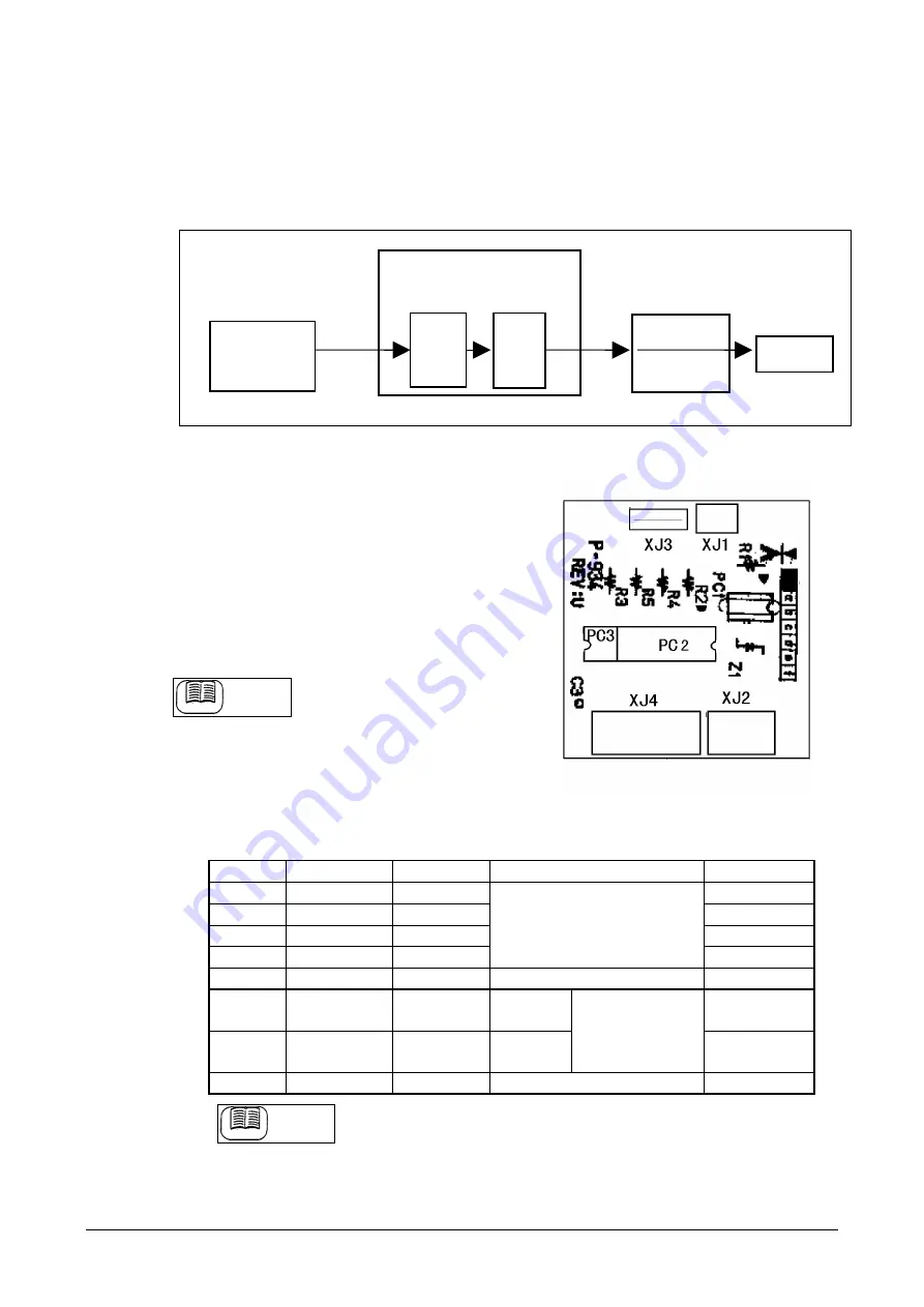
(4) VEX (Load cell 5V)
•
SW (switching) power supply contains noises at the level not influential to the logic circuit.
When it is supplied to the load cell directly, the load cell output also contains noises and
weighing is made unstable. For the countermeasure, a DC/DC converter is incorporated in
the main board so that the voltage is once raised to be regulated by passing through a 5V
regulator.
4.2.4 I/F board P-934-1 (option)
(1) Major parts
•
Output: 4 photo couplers NECPS2501-1 x 4
•
Input : 1 photo couplers NECPS2501-1 x 1
(2) Connector XJ1
⋅
XJ2
⋅
PC1 not mounted
(3) Connector XJ3
•
Used for direct connection with the main
board.
Reference
Reference
Refer to “connector XJ1” of the
main board for PIN No. and signal
code.
[Parts side]
(4) Connector XJ4
PINNo.
Signal code
Wire color
Operational function
to HR12 8P
1
OUT1
Orange
1
2
OUT2
Orange
2
3
OUT3
Orange
3
4
OUT4
Orange
Output selected at “relay
output setup” in Setup Mode
F13.
4
5
COM
Orange
Output common
5
6
IN1 (A)
Orange
Input
anode
6
7
IN1 (C)
Orange
Input
cathode
Input selected at
“relay input
select” in Setup
Mode F14.
7
-
Empty
-
-
8
Reference
Reference
Refer to “relay output setup” in “Setup Mode F13” and “relay input
select” in “Setup Mode F14”, for input/output contents.
SW Power supply
Main board P-932-
A/D board P-933
Load cell
VCC+5V
VEX
+5V
DC/DC
converter
+5.5V
VEX
through
VEX
5V
Regulator


