Chapter 7 ADJUSTMENT MODE
7-10
UNI-3 Service Manual
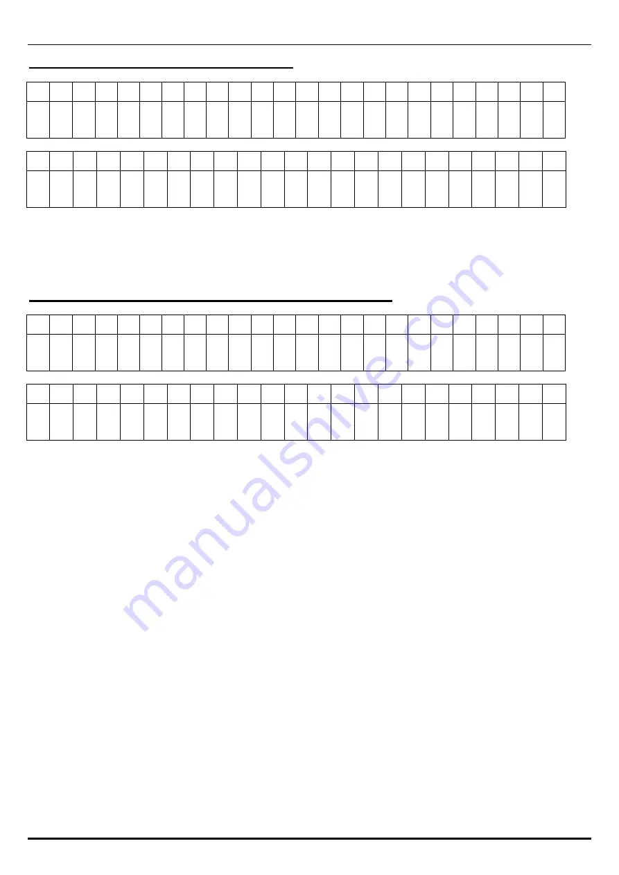
C05-04 BOOT ROM VERSION NO.
The dot display
1
2
3
4
5
6
7
8
9
10 11 12 13 14 15 16 17 18 19 20 21 22 23 24
* B O O T R O M B * * * * #
The segment display
1
2
3
4
5
6
7
8
9
10 11 12 13 14 15 16 17 18 19 20 21 22 23
C 0 5 - 0 4 B O O T R O M B * * * * #
Displays the program No. and the version of the BOOT ROM.
Press the [END] key to return to the menu screen of the hard test.
C05-06 SCALE ROM VERSION NO.(A/D Driver)
The dot display
1
2
3
4
5
6
7
8
9
10 11 12 13 14 15 16 17 18 19 20 21 22 23 24
* S C A L E D R I V E R B * * * * #
The segment display
1
2
3
4
5
6
7
8
9
10 11 12 13 14 15 16 17 18 19 20 21 22 23
C 0 5 - 0 6 S C A L E D R I B * * * * #
Displays the program No. and the version of the A/D DRIVER.
Press the [END] key to return to the menu screen of the hard test.
Displays the version information of weighing driver that processes A/D conversion.
Summary of Contents for Uni-3
Page 10: ...TABLE OF CONTENTS viii UNI 3 Service Manual MEMO ...
Page 18: ...Chapter 1 BASIC INFORMATION 1 8 UNI 3 Service Manual MEMO ...
Page 19: ...Chapter 2 ASSEMBLY DRAWINGS UNI 3 Service Manual 2 1 ASSEMBLY DRAWINGS 2 1 BENCH TYPE L2 2 ...
Page 21: ...Chapter 2 ASSEMBLY DRAWINGS UNI 3 Service Manual 2 3 2 2 BENCH TYPE L1 ...
Page 23: ...Chapter 2 ASSEMBLY DRAWINGS UNI 3 Service Manual 2 5 2 3 POLE TYPE L2 ...
Page 25: ...Chapter 2 ASSEMBLY DRAWINGS UNI 3 Service Manual 2 7 2 4 POLE TYPE L1 ...
Page 30: ...Chapter 3 BLOCK DIAGRAMS 3 4 UNI 3 Service Manual MEMO ...
Page 38: ...Chapter 4 ELECTRICAL SIGNALS 4 8 UNI 3 Service Manual MEMO ...
Page 50: ...Chapter 5 MACHINE DISASSEMBLY 5 12 UNI 3 Service Manual ...


