Chapter 7 ADJUSTMENT MODE
7-70
UNI-3 Service Manual
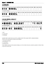
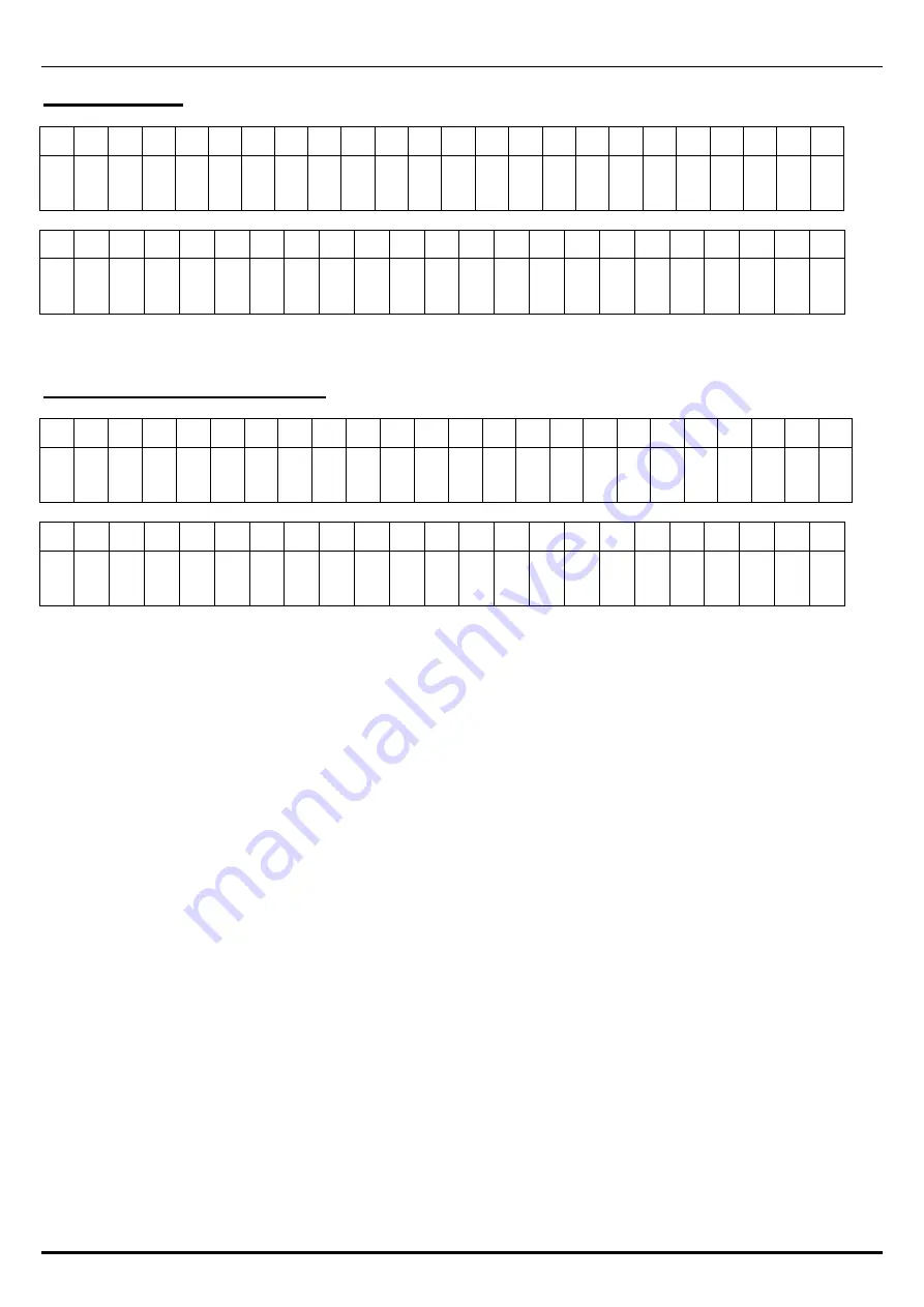
13.MODEL
The dot display
1
2
3
4
5
6
7
8
9
10 11 12 13 14 15 16 17 18 19 20 21 22 23 24
C 1 3 M O D E L
The segment display
1
2
3
4
5
6
7
8
9
10 11 12 13 14 15 16 17 18 19 20 21 22 23
C 1 3 M O D E L
Selects a model flag.
C13-01 MODEL SELECT
The dot display
1
2
3
4
5
6
7
8
9
10 11 12 13 14 15 16 17 18 19 20 21 22 23 24
*
M O D E L S E L E C T
→
1 : B / P
The segment display
1
2
3
4
5
6
7
8
9
10 11 12 13 14 15 16 17 18 19 20 21 22 23
C 1 3 - 0 1 M O D E L 1
1: B/P
2: ELEVATOR
4: HANGING
Specifies the machine mode to accord the operation mode of the program with the installed hardware.
There are three main types of scales as shown below.
1: Bench/Pole (Display)
2: Elevated type
4: Hanging scale
If the machine model and the program settings are not accorded, the scale cannot be operated correctly. Make
sure to accord the mode.
Summary of Contents for Uni-3
Page 10: ...TABLE OF CONTENTS viii UNI 3 Service Manual MEMO ...
Page 18: ...Chapter 1 BASIC INFORMATION 1 8 UNI 3 Service Manual MEMO ...
Page 19: ...Chapter 2 ASSEMBLY DRAWINGS UNI 3 Service Manual 2 1 ASSEMBLY DRAWINGS 2 1 BENCH TYPE L2 2 ...
Page 21: ...Chapter 2 ASSEMBLY DRAWINGS UNI 3 Service Manual 2 3 2 2 BENCH TYPE L1 ...
Page 23: ...Chapter 2 ASSEMBLY DRAWINGS UNI 3 Service Manual 2 5 2 3 POLE TYPE L2 ...
Page 25: ...Chapter 2 ASSEMBLY DRAWINGS UNI 3 Service Manual 2 7 2 4 POLE TYPE L1 ...
Page 30: ...Chapter 3 BLOCK DIAGRAMS 3 4 UNI 3 Service Manual MEMO ...
Page 38: ...Chapter 4 ELECTRICAL SIGNALS 4 8 UNI 3 Service Manual MEMO ...
Page 50: ...Chapter 5 MACHINE DISASSEMBLY 5 12 UNI 3 Service Manual ...


