Chapter 5 MACHINE DISASSEMBLY
UNI-3 Service Manual
5-9
5.
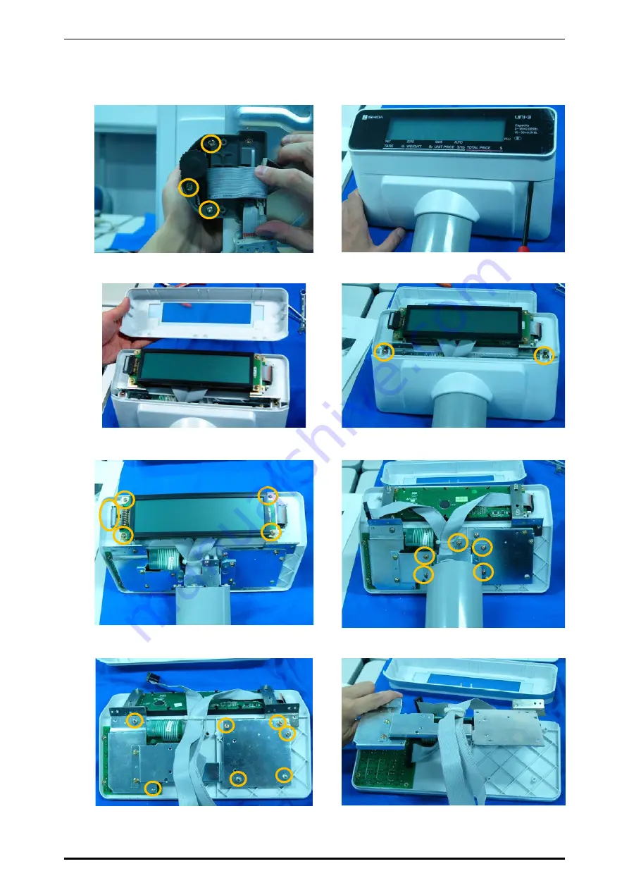
Remove the three screws and detach the
pole unit.
6.
Insert a flat-blade screwdriver into the slit.
7.
Detach the cover.
8.
Remove the two screws and detach the
cover.
9.
Remove the four screws and unplug the
connector to detach the display board.
10.
Remove the five screws and detach the
pole unit.
11.
Remove the seven screws and remove the
plate.
12.
Remove the plate.
Summary of Contents for Uni-3
Page 10: ...TABLE OF CONTENTS viii UNI 3 Service Manual MEMO ...
Page 18: ...Chapter 1 BASIC INFORMATION 1 8 UNI 3 Service Manual MEMO ...
Page 19: ...Chapter 2 ASSEMBLY DRAWINGS UNI 3 Service Manual 2 1 ASSEMBLY DRAWINGS 2 1 BENCH TYPE L2 2 ...
Page 21: ...Chapter 2 ASSEMBLY DRAWINGS UNI 3 Service Manual 2 3 2 2 BENCH TYPE L1 ...
Page 23: ...Chapter 2 ASSEMBLY DRAWINGS UNI 3 Service Manual 2 5 2 3 POLE TYPE L2 ...
Page 25: ...Chapter 2 ASSEMBLY DRAWINGS UNI 3 Service Manual 2 7 2 4 POLE TYPE L1 ...
Page 30: ...Chapter 3 BLOCK DIAGRAMS 3 4 UNI 3 Service Manual MEMO ...
Page 38: ...Chapter 4 ELECTRICAL SIGNALS 4 8 UNI 3 Service Manual MEMO ...
Page 50: ...Chapter 5 MACHINE DISASSEMBLY 5 12 UNI 3 Service Manual ...


