Chapter 6 SETUP MODE
6-1 UNI-3 Service Manual
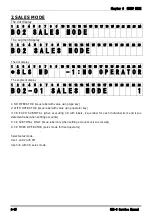
SETUP MODE
The UNI-3 standard specification
The SETUP MODE for this device includes the following items:
1.MACHINE No.
2.SALES MODE
3.PASSWORD
5.DATA STORAGE
6.PRESET REPORT
7.PLU OVERWRITE
8.PLU INITIAL DATA
10.RECEIPT SETTING
11.CASSETTE
12.LABEL SPEC.
13.LABEL FORMAT
14.BARCODE
17.OPERATION SETTING
18.ERROR PROCESS
20.TRACEABILITY
21.DUAL CURRENCY
22.PRICE ROUNDING
23.FREQUENT SHOPPER
26.COUNTRY
27.FILE SAVE/LOAD
28.DATA DISTRIBUTION
29.TAX
31.MODE ACCESS CODE
The menu screen at the head of SETUP MODE
The dot display
1
2
3
4
5
6
7
8
9
10 11 12 13 14 15 16 17 18 19 20 21 22 23 24
< B 0 0 S E T U P >
The segment display
1
2
3
4
5
6
7
8
9
10 11 12 13 14 15 16 17 18 19 20 21 22 23
B 0 0
<
S E T U P
>
Selects menu number.
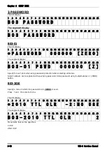
Enter “6000” and press [MODE] key to display the basic menu in the adjustment mode.
Enter the password 495344 and press [PLU] key to release the protection.
All the menus in the adjustment mode are displayed.
Setup mode has functions restricted to the operator and manager.
In order to prevent the operator from making careless setting changes, meter setup changes cannot be
made.To cancel protect, enter the password to make all menus operational.
How to cancel protect:
Operate [PLU] on the main menu screen.
Protect will be cancelled until you return to Normal Mode.
Since protect will be set again if you shutdown once and then return to the main menu, operate the device
after cancelling protect according to the above procedure.
6
Summary of Contents for Uni-3
Page 10: ...TABLE OF CONTENTS viii UNI 3 Service Manual MEMO ...
Page 18: ...Chapter 1 BASIC INFORMATION 1 8 UNI 3 Service Manual MEMO ...
Page 19: ...Chapter 2 ASSEMBLY DRAWINGS UNI 3 Service Manual 2 1 ASSEMBLY DRAWINGS 2 1 BENCH TYPE L2 2 ...
Page 21: ...Chapter 2 ASSEMBLY DRAWINGS UNI 3 Service Manual 2 3 2 2 BENCH TYPE L1 ...
Page 23: ...Chapter 2 ASSEMBLY DRAWINGS UNI 3 Service Manual 2 5 2 3 POLE TYPE L2 ...
Page 25: ...Chapter 2 ASSEMBLY DRAWINGS UNI 3 Service Manual 2 7 2 4 POLE TYPE L1 ...
Page 30: ...Chapter 3 BLOCK DIAGRAMS 3 4 UNI 3 Service Manual MEMO ...
Page 38: ...Chapter 4 ELECTRICAL SIGNALS 4 8 UNI 3 Service Manual MEMO ...
Page 50: ...Chapter 5 MACHINE DISASSEMBLY 5 12 UNI 3 Service Manual ...


