Chapter 8 ADJUSTMENT MODE
6.
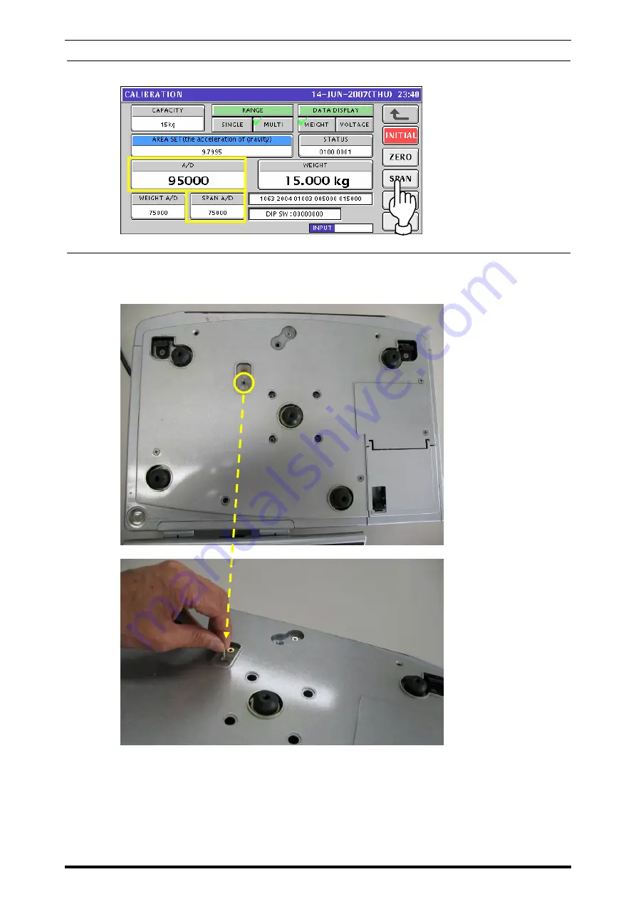
Repeat steps 3 through 5 above several times until the A/D display field shows “95000”,
and the SPAN A/D display field shows ”75000”.
7.
To memorize the adjusted span value, press the Memory button located on the main
board inside of the machine with a nonconductive and thin material such a wooden stick
through the hole on the upper case.
8-18
UNI-7 Service Manual
Summary of Contents for UNI-7
Page 12: ...TABLE OF CONTENTS x UNI 7 Service Manual ...
Page 22: ...Chapter 1 BASIC INFORMATION 1 10 UNI 7 Service Manual ...
Page 23: ...Chapter 2 ASSEMBLY DRAWINGS 2 ASSEMBLY DRAWINGS 2 1 BENCH TYPE UNI 7 Service Manual 2 1 ...
Page 25: ...Chapter 2 ASSEMBLY DRAWINGS 2 2 POLE TYPE UNI 7 Service Manual 2 3 ...
Page 27: ...Chapter 2 ASSEMBLY DRAWINGS 2 3 BAKERY TYPE UNI 7 Service Manual 2 5 ...
Page 30: ...Chapter 2 ASSEMBLY DRAWINGS 2 5 ELEVATED SINGLE PRINTER TYPE 2 8 UNI 7 Service Manual ...
Page 32: ...Chapter 2 ASSEMBLY DRAWINGS 2 6 ELEVATED DUAL PRINTER TYPE 2 10 UNI 7 Service Manual ...
Page 34: ...Chapter 2 ASSEMBLY DRAWINGS 2 12 UNI 7 Service Manual ...
Page 36: ...Chapter 3 BLOCK DIAGRAMS 3 2 BLOCK DIAGRAM BAKERY TYPE 3 2 UNI 7 Service Manual ...
Page 37: ...Chapter 3 BLOCK DIAGRAMS 3 3 BLOCK DIAGRAM SELF SERVICE TYPE UNI 7 Service Manual 3 3 ...
Page 38: ...Chapter 3 BLOCK DIAGRAMS 3 4 BLOCK DIAGRAM HANGING TYPE 3 4 UNI 7 Service Manual ...
Page 40: ...Chapter 3 BLOCK DIAGRAMS Dual Printer 3 6 UNI 7 Service Manual ...
Page 58: ...Chapter 4 ELECTRICAL SIGNALS 4 18 UNI 7 Service Manual ...
Page 96: ...Chapter 5 MACHINE DISASSEMBLY 5 38 UNI 7 Service Manual ...
Page 126: ...Chapter 7 SETUP MODE 7 24 UNI 7 Service Manual ...
Page 141: ...Chapter 7 SETUP MODE UNI 7 Service Manual 7 39 ...
Page 144: ...Chapter 8 ADJUSTMENT MODE 8 2 UNI 7 Service Manual ...
Page 176: ...Chapter 9 ERROR SCREENS 9 8 UNI 7 Service Manual ...


