1.
Install Load Limiter device
to the non
-
moving rope/
chain near to the anchor/suspension point on a
slacked (non
-
loaded) hoist.
2.
Torque rope clamps down
. Cotter pins are simply to
keep the unit in place.
3.
For preset units
see
“
sizing overload limit devices
”.
4.
The normally closed contact wires should be
placed in series
with an appropriate part of the hoist
circuitry usually the contactor coil of the UP contactor.
As the load increases the switch will open at the ap-
proximate setting and shut down the movement of the
hoist in the UP direction. Slack Load option is put in
the DOWN circuit of the hoist.
5.
Hysteresis:
All electro
-
mechanical devices exhibit
hysteresis such that to RESET it is likely that the
load must decrease below the
“
trip point
”
in order
to reset.
6.
Repair
of any Load Limit device should not be at-
tempted except for superficial problems such as a cut
wire etc. NEVER disassemble and reassemble any
unit. The
“
link
”
pins on the Chain Load Limit devices
are of special grade steel and should never be modi-
fied or replaced with other than factory supplied parts.
Installation of Load Limiters
485 Dundee Avenue, Suite 85
East Dundee, IL 60118, USA
Phone: 847-836-8844
Fax:847-428-9379
INDUSTRY SOLUTIONS
I N T E R N A T I O N A L, I N C.
561 Plate Drive, #5
East Dundee, IL 60118, USA
Phone: 847
-
836
-
8844
Fax: 847
-
428
-
9379
Model
* Best Torque
Socket
LL18, LL28
8 Nm or 5.9 Ft. Lbs.
13mm
LL45, LL60
10 Nm or 7.4 Ft. Lbs.
16mm
LL80, LL150, LL200
15 Nm or 11.1 Ft. Lbs.
19mm
table 3
Rope Clamp Bolt Torque Rating
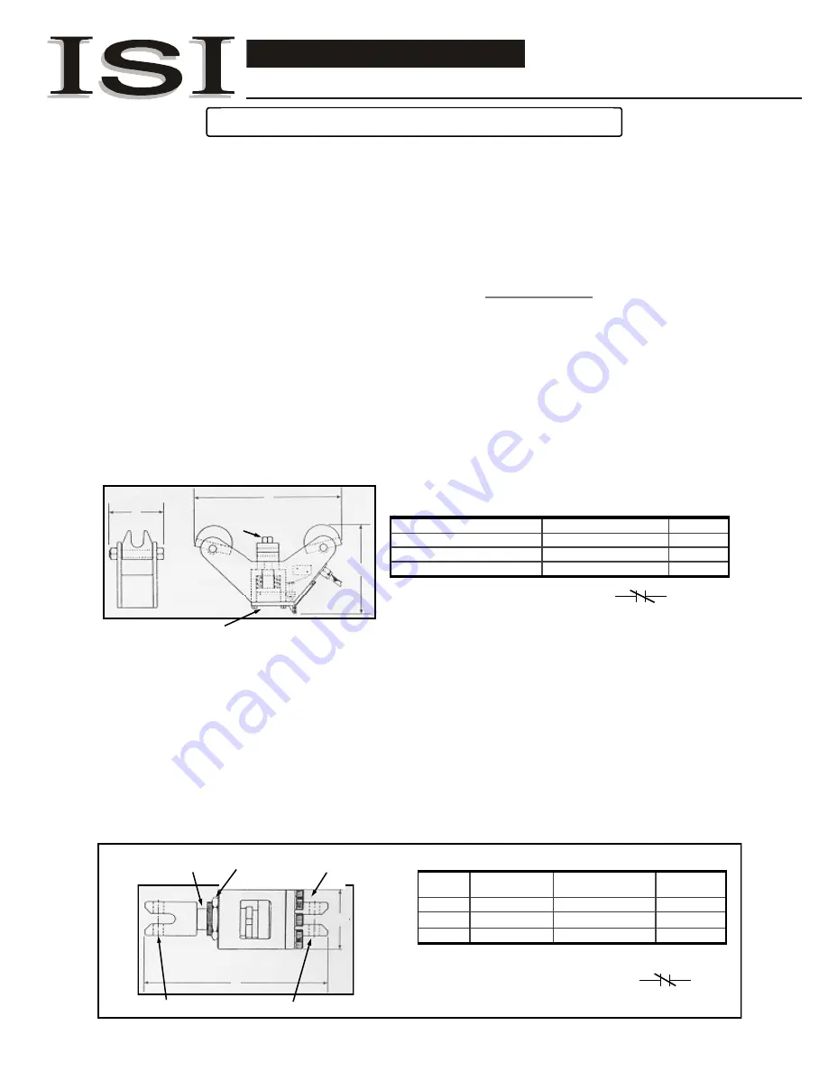
fig. 3b Wire rope Hoist Load Limit-
er showing internal mechanics,
rope clamp and cover plate for
adjusting screw.
WIRE ROPE STYLE
C
B
A
Protective cover plate for adjustment screw.
WIRE ROPE STYLE
-
Setting in the field:
a.
Detach the back protection plate.
b.
Pick up the heaviest load required ensuring that it is not more than the safe working load of the crane &
hoist combination.
c.
Turn the adjusting screw (under protective cover plate) out fully, pick up safe working load, turn adjusting
screw in until cut out then turn back about 1/8 turn and lock. The adjusting screw is very sensitive.
d.
Lower the load and lift up again to ensure correct functioning. Do this several times as a check. You may
have to fine tune several times.
* USE TORQUE WRENCH to put cable clamp on hoist!
e.
Reattach back protective plate.
(see
* Best Torque below)
Model
Link Pins
Allen Hex
Adjusting Collar
Lock Nut
LL12C
6mm 13mm
19mm
38mm
LL17C
10mm 19mm
25mm
50mm
LL28C
10mm 19mm
25mm
50mm
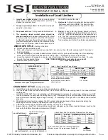
table 4 Chain Link Pin, Adjusting Collar and Lock Nut sizes
fig. 4b
Chain hoist load limiter showing adjustment
collar lock nut and link pin placement (included).
CHAIN STYLE
LOCK NUT –do not adjust
all the way out.
ADJUSTING COLLAR
B
A
LINK PIN PLACEMENT—
-
ONLY USE ISI SUPPLED !!!!
CHAIN HOIST STYLE
–
Setting in the field:
a.
Install Chain Load Limiter device using Link pins provided, see table 4.
b.
Use the heaviest load required ensuring that it is not more than the safe working load of the crane and hoist
combination.
c.
LOOSEN LOCK NUT. Turn the adjusting nut IN (clockwise) to increase the chain load setting and or OUT
(counter
-
clockwise) to decrease the setting (see
fig 4b
). The adjusting nut is very sensitive and a small adjust-
ment will cause a relatively large change in setting. The adjusting nut is tight and is constantly under internal
pressure.
d.
When desired cut out point is reached, the N.C. contact will open (test several times to assure setting), the
adjusting nut must be locked by tightening the lock nut (
see fig 4b
).
e.
CHECK load cut out again to ensure proper setting. You may have to fine tune.
f.
Ensure that any hoist
“
top
”
limit switches are set and arranged so the Chain load limit device could not be
broken by the bottom block when at maximum lift height.
Clamp bolt
fig. 3b
fig. 4b
© 201
9
Industry Solutions International, Inc.
Prices and specifications are subject to change without notice.
N.C. Circuit
N.C. Circuit
1
201
9
060
3
B


